

Read and download the CBSE Class 12 Physics Electromagnetic Induction And Alternating Current Worksheet Set 02 in PDF format. We have provided exhaustive and printable Class 12 Physics worksheets for Chapter 6 Electromagnetic Induction, designed by expert teachers. These resources align with the 2026-27 syllabus and examination patterns issued by NCERT, CBSE, and KVS, helping students master all important chapter topics.
Chapter-wise Worksheet for Class 12 Physics Chapter 6 Electromagnetic Induction
Students of Class 12 should use this Physics practice paper to check their understanding of Chapter 6 Electromagnetic Induction as it includes essential problems and detailed solutions. Regular self-testing with these will help you achieve higher marks in your school tests and final examinations.
Class 12 Physics Chapter 6 Electromagnetic Induction Worksheet with Answers

Important Questions for NCERT Class 12 Physics Electromagnetic Induction
Question. A rectangular coil of 20 turns and area of cross-section 25 sq. cm has a resistance of 100 W. If a magnetic field which is perpendicular to the plane of coil changes at a rate of 1000 tesla per second, the current in the coil is
(a) 1 A
(b) 50 A
(c) 0.5 A
(d) 5 A
Answer C
Question. A conducting square frame of side ‘a’ and a long straight wire carrying current I are located in the same plane as shown in the figure. The frame moves to the right with a constant velocity ‘V’. The emf induced in the frame will be proportional to
(a) 1/(2x + a)2
(b) 1/(2x − a)(2x + a)
(c) 1/x2
(d) 1/(2x − a)2
Answer B
Question. If N is the number of turns in a coil, the value of self inductance varies as
(a) N 0
(b) N
(c) N 2
(d) N–2
Answer C
Question. A magnetic field of 2 × 10⁻² T acts at right angles to a coil of area 100 cm2, with 50 turns. The average e.m.f. induced in the coil is 0.1 V, when it is removed from the field in t sec. The value of t is
(a) 10 s
(b) 0.1 s
(c) 0.01 s
(d) 1 s
Answer B
Question. An electron moves on a straight line path XY as shown. The abcd is a coil adjacent to the path of electron. What will be the direction of current, if any, induced in the coil?
(a) The current will reverse its direction as the electron goes past the coil
(b) No current induced
(c) abcd
(d) adcb
Answer A
Question. Two coils of self inductance 2 mH and 8 mH are placed so close together that the effective flux in one coil is completely linked with the other.
The mutual inductance between these coils is
(a) 16 mH
(b) 10 mH
(c) 6 mH
(d) 4 mH
Answer D
Question. A metal ring is held horizontally and bar magnet is dropped through the ring with its length along the axis of the ring. The acceleration of the falling magnet is
(a) more than g
(b) equal to g
(c) less than g
(d) either(a) or (c)
Answer C
Question. Faraday’s laws are consequence of conservation of
(a) energy
(b) energy and magnetic field
(c) charge
(d) magnetic field
Answer A
Question. A conducting rod AB moves parallel to X-axis in a uniform magnetic field, pointing in the positive X-direction. The end A of the rod gets
(a) positively charged
(b) negatively charged
(c) neutral
(d) first positively charged and then negatively charged
Answer A
Important Questions for NCERT Class 12 Physics Alternating Induction
Question. In an a.c. circuit the e.m.f. (e) and the current (i) at any instant are given respectively by e = E0sinwt , i = I0sin(wt – f)
The average power in the circuit over one cycle of a.c. is
(a) E0I0 /2 cosΦ
(b) E0I0
(c) E0I0/2
(d) E0I0 /2 sinΦ
Answer A
Question. A coil of inductive reactance 31 W has a resistance of 8 W. It is placed in series with a condenser of capacitative reactance 25 W. The combination is connected to an a.c. source of 110 V. The power factor of the circuit is
(a) 0.33
(b) 0.56
(c) 0.64
(d) 0.80
Answer D
Question. The mutual inductance of a pair of coils, each of N turns, is M henry. If a current of I ampere in one of the coils is brought to zero in t second, the emf induced per turn in the other coil, in volt, will be A
(a) MI /t
(b) NMI/t
(c) MN /It
(d) MI/Nt
Answer A
Question. For a series LCR circuit, the power loss at resonance is
(a) V2 /[ωL - 1/ωC]
(b) I2 Lω
(c) I2R
(d) V2/ Cω
Answer C
Question. In an a.c. circuit with phase voltage V and current I, the power dissipated is
(a) V.I
(b) depends on phase angle between V and I
(c) 1/2 ×V.I
(d) 1/√2 ×V.I
Answer B
Question. A step down transformer is connected to 2400 volts line and 80 amperes of current is found to flow in output load. The ratio of the turns in primary and secondary coil is 20 : 1. If transformer efficiency is 100%, then the current flowing in the primary coil will be
(a) 1600 amp
(b) 20 amp
(c) 4 amp
(d) 1.5 amp
Answer C
Question. An series L-C-R circuit is connected to a source of A.C. current. At resonance, the phase difference between the applied voltage and the current in the circuit, is
(a) p
(b) zero
(c) p/4
(d) p/2
Answer B
Question. A bar magnet is being moved towards a stationary coil (i) rapidly (ii) slowly:
a. larger in case (i)
b. smaller in case (ii)
c. equal in both cases
d. cannot say
Answer : A, B
Question. In which of the following cases with a bar magnet and the solenoid, an induced emf is generated?
a. when magnet is withdrawn from the solenoid
b. when magnet is inserted into the solenoid
c. when solenoid is moved towards or away from the magnet
d. when both the solenoid and magnet are moved in the same direction with the same speed
Answer : A, B, C
Question. Eddy currents produced in a conductor are responsible for:
a. damping
b. heating
c. sparking
d. loss of energy
Answer : A, B, D
Question. Two solenoids have identical geometrical constructions put one is made of thick wire and the other of thin wire.
Which of the following quantities are different for the two solenoids?
a. self inductance
b. rate of joule heating if the same current goes through them
c. magnetic field energy if the same current goes through them
d. time constant if one solenoid is connected to one battery and the other is connected to another battery
Answer : B, D
Question. Two different coils have self-inductances L1 = 8mH, L2 = 2mH. The current in one coil is increased at a constant rate. The current in the second coil is also increased at the same constant rate. At a certain instant of time, the power given to the two coils is the same. At that time the current, the induced voltage and the energy stored in the first coil are i1, V1 and W1 respectively. Corresponding values for the second coil at the same instant are i1, V2 and W2 respectively. Then
a. i1/i2 = 1/4
b. i1/i2 = 4
c. W2/W1 = 4
d. V2/V1 = 1/4
Answer : A, C, D
Question. Which of the following is/are equal to Henry?
a. Volt second/ampere
b. Volt (second)2 /coulomb
c. Volt² second/coulomb
d. Joule (second)2 / (coulomb)2
Answer : A, B, D
Question. If R, C and L be the resistance, capacitance and inductance in a circuit in which a.c. of frequency f is set up then which of the following has the dimensions of R?
a. f C
b. f L
c. 1/fC
d. L/f
Answer : B, C
Question. A series R-C circuit is connected to AC voltage source. Consider two cases; a. when C is without a dielectric medium and b. when C is filled with dielectric of constant 4. The current R I through the resistor and voltage C V across the capacitor are compared in the two cases. Which of the following is/are true?
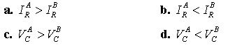
Answer : B, C
Question. A bar magnet is moved along the axis of a copper ring placed far away from the magnet. Looking from the side of the magnet, an anticlockwise current is found to be induced in the ring. Which of the following may be true?
a. The south-pole faces the ring and the magnet moves towards it
b. The north-pole faces the ring and the magnet moves towards it
c. The south-pole faces the ring and the magnet moves away from it
d. The north-pole faces the ring and the magnet moves away from it
Answer : B, C
Question. If R, C and L denote the resistance, capacitance and inductance, which of the following will have the dimensions of frequency?
a. RL−1
b. R−1 C−1
c. L−1/2 C−1/2
d. RCL
Answer : A, B, C
Comprehension Based
Paragraph-I
The capacitor of capacitance C can be charged (with the help of a resistance R) by a voltage source V, by closing switch S1 while keeping switch S2 open. The capacitor can be connected in series with an inductor L by closing switch S2 and opening S1.
Question. Initially, the capacitor was uncharged. Now, switch S1 is closed and S2 is kept open. If time constant of this circuit is τ, then
a. after time interval τ, charge on the capacitor is CV/2
b. after time interval 2τ , charge on the capacitor is CV(−e−2)
c. the work done by the voltage source will be half of the heat dissipated when the capacitor is fully charged
d. after time interval 2τ , charge on the capacitor is CV(−e−2)
Answer : B
Question. After the capacitor gets fully charged, S1 is opened and S2 is closed so that the inductor is connected in series with the capacitor. Then,
a. at t = 0, energy stored in the circuit is purely in the form of magnetic energy
b. at any time t > 0, current in the circuit is in the same direction
c. at t > 0, there is no exchange of energy between the inductor and capacitor
d. at any time t > 0, maximum instantaneous current in the circuit may be V √C/L
Answer : D
Question. If the total charges stored in the LC circuit is 0 Q , then for t ≥ 0
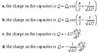
Answer : C
Paragraph – II
A point charge Q is moving in a circular orbit of radius R in the x-y plane with an angular velocityω. This can be considered as equivalent to a loop carrying a steady current . Qω / 2π A uniform magnetic field along the positive z-axis is now switched on, which increases at a constant rate from 0 to B in one second. Assume that the radius of the orbit remains constant. The applications of the magnetic field induces an emf in the orbit.
The induced emf is defined as the work done by an induced electric field in moving a unit positive charge around a closed loop. It is known that, for an orbiting charge, the magnetic dipole moment is proportional to the angular momentum with proportionality constantγ.
Question. The magnitude of the induced electric field in the orbit at any instant of time during the time interval of the magnetic field change is:
a. BR/4
b. −BR/2
c. BR
d. 2BR
Answer : C
Question. The change in the magnetic dipole moment associated with the orbit, at the end of the time interval of the magnetic field change, is:
a. γ (BQR2/2)
b. - γ (BQR2/2)
c. γ (BQR2/2)
d. γ BQR2
Answer : B
Paragraph –III
A thermal power plant produces electric power of 600 kW at 4000 V, which is to be transported to a place 20 km away from the power plant for consumer’ usage. It can be transported either directly with a cable of large current carrying capacity or by using a combination of step-up and step-down transformers at the two ends. The drawback of the direct transmission is the large energy dissipation is much smaller. In this method, a step -up transformer is used at the plant side so that the current is reduced to a smaller value. At the consumer’s end a step-down transformer is used to supply power to the consumers at the specified lower voltage. It is reasonable to assume that the power cable is purely resistive and the transformers are ideal with a power factor unity. All the current and voltages mentioned are rms values.
Question. If the direct transmission method with a cable of resistance 1 0.4 km) − is used, the power dissipation (in %) during transmission is:
a. 20
b. 30
c. 40
d. 50
Answer : B
Question. In the method using the transformers, assume that the ratio of the number of turns in the primary to that in the secondary in the step-up transformer is 1 : 10. If the power to the consumers has to be supplied at 200V, the ratio of the number of turns in the primary to that in the secondary in the step-down transformer is:
a. 200 : 1
b. 150 : 1
c. 100 : 1
d. 50 : 1
Answer : A
Paragraph –IV
A point charge Q is moving in a circular orbit of radius R in the x-y plane with an angular velocity ω. This can be considered as equivalent to a loop carrying a steady current .Qω/2π. A uniform magnetic field along the positive z-axis is now switched on, which increases at a constant rate from 0 to B in one second. Assume that the radius of the orbit remains constant. The applications of the magnetic field induces an emf in the orbit. The induced emf is defined as the work done by an induced electric field in moving a unit positive charge around a closed loop. It is known that, for an orbiting charge, the magnetic dipole moment is proportional to the angular momentum with a proportionality constant γ
.
Question. The magnitude of the induced electric field in the orbit at any instant of time during the time interval of the magnetic field change is:
a. BR/4
b. −BR/2
c. BR
d. 2BR
Answer : B
Question. The change in the magnetic dipole moment associated with the orbit, at the end of the time interval of the magnetic field change, is:
a. −γ BQR2
b. −γ(BQR2/2)
c. γ(BQR2/2)
d. γ BQR2
Answer : B
Integer
Question. The sum and difference of self inductance of two coils are 13 mH and 5 mH respectively. What is the maximum value of mutual inductance of the two coils?
Answer : 6
Question. A transformer working on 220 V a.c. line gives an output current of 4 A at 55 V. What is the primary current?
Assume that there is no loss of energy.
Answer : 1
Question. The magnetic flux of φ (in weber) in a closed circuit of resistance 3 ohm varies with time t (in second) according to the equation φ = 2t2 −10t + 3. What will be the magnetic of induced current at t = 0.25 s ?
Answer : 3
Question. An a.c. generator gives an output voltage of E = 170sin 56⋅52t.What is the frequency of alternating voltage produced?
Answer : 9
Question. A condenser of capacitance 0.144pH is used in a transmitter to transmit at wavelength λ. If inductance of 2 1/π mH is used for resonance, what is the value of λ?
Answer : 7
Question. In the series RLC circuit as shown in Fig., what would be the ammeter reading?
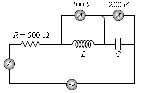
Answer : 2
Question. An a.c. source of frequency 1000 Hz is connected to a coil of 200/π mH and negligible resistance. If effective current through the coil is 7.5 mA, what is the voltage across the coil?
Answer : 3
Question 401. Define magnetic flux. Write its S.I. unit. Is it a scalar or vector quantity?
Answer: Magnetic flux (\( \Phi_B \)) is defined as the measure of the total number of magnetic field lines passing normally through a given cross-sectional area.
Mathematically, it is expressed as: \[ \Phi_B = \vec{B} \cdot \vec{A} = B A \cos\theta \] where \( B \) is the magnetic field strength, \( A \) is the area of the surface, and \( \theta \) is the angle between the magnetic field vector and the normal to the surface.
* **SI Unit:** **Weber (Wb)** (or Tesla-meter squared, \( \text{T}\cdot\text{m}^2 \)).
* **Type of quantity:** It is a **scalar** quantity.
In simple words: Magnetic flux measures how much magnetic field is flowing through a specific surface area, similar to water flowing through a net. It is a scalar quantity measured in Webers.
Exam Tip: Remember that although magnetic field and area are vectors, their dot product yields a scalar magnetic flux.
Question 402. (i) What is electromagnetic induction ?
(ii) Describe, with the help of a suitable diagram, how one can demonstrate that emf can be induced in a coil due to the change of magnetic flux.
Answer: The explanations and experimental details are:
(i) **Electromagnetic Induction:** It is the phenomenon of generating an electromotive force (emf) and consequently inducing an electric current in a closed conducting loop whenever the magnetic flux linked with that loop changes over time.
(ii) **Experimental Demonstration:**
Consider a conducting coil of several turns connected in series to a sensitive center-zero galvanometer.
1. When we push the North pole of a permanent bar magnet towards the coil, the magnetic flux linked with the coil increases. This causes a sudden momentary deflection in the galvanometer pointer (e.g., to the right), showing that an electromotive force (emf) and current have been induced.
2. If the magnet is held completely still inside or near the coil, the flux remains constant, and the galvanometer pointer returns to zero.
3. When we pull the North pole of the magnet away from the coil, the magnetic flux decreases, causing the galvanometer pointer to deflect in the opposite direction (e.g., to the left). This simple demonstration confirms that a changing magnetic flux induces an emf inside a closed loop.
In simple words: (i) Electromagnetic induction is the way we generate electricity by wiggling a magnet near a coil of wire. (ii) When you slide a magnet in or out of a wire coil, the changing magnetic fields create a temporary electric current that you can see as a twitch on a connected meter.
Exam Tip: Clearly label the direction of the magnet's motion (\( \vec{v} \)) and the resulting pointer deflection on your sketch to illustrate the experiment thoroughly.
Question 403. State Faraday’s laws of electromagnetic induction.
Answer: Faraday's laws of electromagnetic induction consist of two core statements:
1. **First Law:** Whenever the magnetic flux linked with a conducting circuit changes over time, an emf is induced in the circuit. This induced emf persists as long as the change in magnetic flux continues.
2. **Second Law:** The magnitude of the induced emf \( e \) is directly proportional to the time rate of change of magnetic flux \( \Phi_B \) linked with the circuit: \[ e = -N \frac{d\Phi_B}{dt} = -N \frac{\Phi_2 - \Phi_1}{t} \] where \( N \) is the number of turns in the coil, and the negative sign indicates opposition to the change (per Lenz's law).
In simple words: 1. You only get an induced voltage while the magnetic field is actively changing. 2. The faster the magnetic field changes, or the more loops of wire you have, the higher the generated voltage will be.
Exam Tip: Do not forget to include the negative sign in the mathematical equation and explain that it represents Lenz's law.
Question 404. When a bar magnet is pushed towards or away from the coil connected to a galvanometer, pointer in galvanometer deflects. Identify the phenomenon causing this deflection and write the factors on which the amount and direction of the deflection depends.
Answer: The details are:
* **Phenomenon:** The phenomenon is **Electromagnetic Induction**.
* **Factors affecting the amount (magnitude) of deflection:**
1. The speed with which the bar magnet is moved relative to the coil (faster motion causes larger deflection).
2. The strength of the permanent bar magnet.
3. The total number of turns in the conducting coil.
* **Factors affecting the direction of deflection:**
1. The direction of relative motion (moving the magnet towards versus away from the coil reverses the deflection direction).
2. The magnetic pole facing the coil (North pole versus South pole).
In simple words: The twitching meter is caused by electromagnetic induction. Moving the magnet faster or using a stronger magnet makes the needle jump further. Moving it away instead of towards, or flipping the magnet's poles, makes the needle jump in the opposite direction.
Exam Tip: Divide your factors clearly into "magnitude" and "direction" sections to score maximum marks.
Question 405. A rectangular loop and a circular loop are moving out of a uniform magnetic field region to a field-free region with a constant velocity v. In which loop do you expect the induced emf to be constant during the passage out of the field region? The field is normal to the loops.
Answer: The induced emf will be constant in the **rectangular loop**.
**Reason:**
The induced motional emf \( e \) is given by the rate of change of magnetic flux: \[ e = B \frac{dA}{dt} \] For a rectangular loop leaving the field at a constant velocity \( v \), the rate of change of its area within the magnetic field region is constant (\( \frac{dA}{dt} = \text{constant} \)), resulting in a steady, constant emf.
In contrast, for a circular loop, the rate at which its area exits the field region is not constant because of its curved boundary geometry. Thus, its induced emf will vary continuously as it slides out.
In simple words: The rectangular loop has straight, uniform sides, so its area exits the magnetic field at a perfectly steady rate, making its generated voltage completely constant. The circular loop's curved sides mean its area exits unevenly, causing its voltage to fluctuate.
Exam Tip: Use the formula \( e = B l v \) for the rectangular loop to show that the length of the moving arm crossing the field lines remains constant, unlike the circular loop.
Question 406. State Lenz’s law.
Answer: Lenz's law states that the direction of the induced electric current (or induced electromotive force) in a closed conducting loop is always such that it electromagnetically opposes the very change in magnetic flux that is responsible for creating it.
In simple words: Lenz's law says that nature fights back. Any induced current will create its own magnetic field that tries to block whatever magnetic change started it in the first place.
Exam Tip: Note that Lenz's law is a direct consequence of the law of conservation of energy.
Question 407. Illustrate by giving an example, how Lenz’s law helps in predicting the direction of the current in a loop in the presence of a changing magnetic flux ?
Answer: **Illustration (Moving a Magnet toward a Coil):**
Consider a closed metallic loop.
1. When we push the North (N) pole of a bar magnet towards the face of the loop, the magnetic flux passing through the loop increases.
2. According to Lenz's law, the induced current in the loop must oppose this increasing magnetic flux. To do so, the loop creates its own North pole on the facing side to repel the incoming magnet.
3. Using the clock face rule, a North pole corresponds to a current flowing in the **counter-clockwise (anti-clockwise)** direction.
4. Conversely, if we pull the North pole away, the loop tries to attract it by creating a South pole on the facing side, causing current to flow in the **clockwise** direction.
In simple words: When you push a North pole toward a ring, the ring creates its own North pole to push back, making the current spin counter-clockwise. When you pull the magnet away, the ring switches to a South pole to pull it back, making the current spin clockwise.
Exam Tip: Draw a simple diagram showing the loops with 'N' (anticlockwise arrows) and 'S' (clockwise arrows) to visually support your explanation.
Question 408. Predict the polarity of the capacitor in the situation described below :
Answer: The polarities are:
* **Plate A:** **Positive polarity**
* **Plate B:** **Negative polarity**
**Reasoning:**
As the North pole of the left magnet moves towards the coil, the left face of the loop must develop a North pole to oppose its entry. This induces a counter-clockwise current on the left. At the same time, the South pole of the right magnet is moving towards the right side of the coil, prompting that face to develop a South pole to repel it, inducing a clockwise current when viewed from the right. Tracing this combined flow shows that the induced current leaves plate B and enters plate A, accumulating positive charge on **Plate A** and negative charge on **Plate B**.
In simple words: Pushing the magnets towards the coil induces currents that charge up the capacitor. The current flow ends up pushing positive charge onto plate A and pulling it away from plate B.
Exam Tip: Write down the polarities clearly as "A - positive" and "B - negative" to make it straightforward to grade.
Question 409. A bar magnet is moved in the direction indicated by the arrow between two coils PQ and CD. Predict the direction of the induced current in each coil.
Answer: As the bar magnet moves to the left (with its North pole moving away from coil CD and its South pole moving towards coil PQ):
1. **In Coil PQ (left):** The approaching South pole causes the right-facing end of coil PQ to develop a South pole to repel it. This corresponds to a **clockwise** current when viewed from the right (moving **from Q to P** through the galvanometer/ammeter).
2. **In Coil CD (right):** The departing North pole causes the left-facing end of coil CD to develop a South pole to attract it. This corresponds to a **clockwise** current when viewed from the left (moving **from D to C** through the galvanometer/ammeter).
In simple words: As the magnet slides left, it pushes its South pole into the left coil and pulls its North pole away from the right coil. Both coils generate clockwise currents (from Q to P and from D to C) to resist this magnetic movement.
Exam Tip: Use the clock face rule (S is clockwise, N is anticlockwise) to determine the exact direction of the current arrows in both coils.
Question 410. The electric current flowing in a wire in the direction from B to A is decreasing. Find out the direction of the induced current in the metallic loop kept above the wire as shown.
Answer: According to the right-hand grip rule, the magnetic field produced by the straight wire (carrying current from B to A, i.e., to the left) inside the loop above it is directed perpendicularly **into the page** (\( \otimes \)).
Since this current is decreasing, the magnetic flux pointing into the page is decreasing.
According to Lenz's law, the loop opposes this decrease by generating a magnetic field pointing perpendicularly **into the page** (\( \otimes \)).
This requires the induced current in the loop to flow in the **clockwise** direction.
In simple words: The wire's leftward current creates a magnetic field pointing into the page inside the loop. As this current fades, the loop generates a clockwise current to prop up the fading field.
Exam Tip: Be very careful with the right-hand grip rule orientation: pointing your thumb along the current direction shows the circular field lines curl into the page above the wire.
Question 411. A conducting loop is held above a current carrying wire PQ as shown in the figure. Depict the direction of the current induced in the loop when the current in the wire PQ is constantly increasing.
Answer: The current in the wire PQ flows from left to right (P to Q).
1. By the right-hand grip rule, the magnetic field produced by this current in the region above the wire (inside the loop) is directed perpendicularly **out of the page** (\( \odot \)).
2. Since the current in wire PQ is constantly increasing, this outward magnetic flux is also increasing.
3. To oppose this increase, Lenz's law states the induced current must generate a magnetic field directed **into the page** (\( \otimes \)).
4. This requires the induced current in the loop to flow in the **clockwise** direction.
In simple words: The wire's rightward current creates an upward magnetic field pointing out of the page. Since the current is increasing, the loop fights this build-up by running a clockwise current to push the field back into the page.
Exam Tip: Clearly state both steps: first find the direction of the initial field, then apply Lenz's law to find the opposing induced field direction.
Question 412. A conducting loop is held below a current carrying wire PQ as shown in the figure. Predict the direction of the induced current in the loop when the current in the wire PQ is constantly increasing.
Answer: The current in wire PQ flows from left to right (P to Q).
1. By the right-hand grip rule, the magnetic field produced in the region below the wire (where the loop is located) is directed perpendicularly **into the page** (\( \otimes \)).
2. Because the current in wire PQ is constantly increasing, this inward magnetic flux is increasing over time.
3. According to Lenz's law, the loop opposes this increase by generating a magnetic field pointing perpendicularly **out of the page** (\( \odot \)).
4. This requires the induced current in the loop to flow in the **counter-clockwise (anti-clockwise)** direction.
In simple words: Below the wire, the magnetic field points into the page. As the current grows, the loop resists the growing inward field by running a counter-clockwise current to generate its own outward-pointing field.
Exam Tip: Note how the position of the loop (above versus below the wire) flips the direction of the magnetic field and thus the induced current.
Question 413. What is the direction of induced currents in metal rings 1 and 2 when current I in the wire is increasing steadily ?
Answer: The wire carries current from left to right.
* **In Ring 1 (above the wire):** The magnetic field points out of the page (\( \odot \)). Since the current is increasing, the outward flux is increasing. To oppose this, the ring creates an inward field (\( \otimes \)), which corresponds to a **clockwise** induced current.
* **In Ring 2 (below the wire):** The magnetic field points into the page (\( \otimes \)). Since the current is increasing, the inward flux is increasing. To oppose this, the ring creates an outward field (\( \odot \)), which corresponds to a **counter-clockwise (anti-clockwise)** induced current.
In simple words: Ring 1 (above) runs a clockwise current to resist the growing field pointing out of the page. Ring 2 (below) runs a counter-clockwise current to resist the growing field pointing into the page.
Exam Tip: Label the answer for both Ring 1 and Ring 2 explicitly to make it easy for the examiner to award full marks.
Question 414. The closed loop (PQRS) of wire is moved in to a uniform magnetic field at right angles to the plane of the paper as shown in figure. Predict the direction of the induced current in the loop.
Answer: The uniform magnetic field points perpendicularly into the page (\( \otimes \)).
1. As the rectangular loop \( PQRS \) is moved into this field, the magnetic flux linked with the loop increases.
2. To oppose this increase, Lenz's law dictates that the loop must generate its own magnetic field pointing perpendicularly out of the page (\( \odot \)).
3. This requires the induced current in the loop to flow in the **counter-clockwise (anti-clockwise)** direction (i.e., along the path \( PSRQ \)).
In simple words: Moving the loop into the field increases the inward magnetic lines passing through it. The loop fights this increase by running a counter-clockwise current to push magnetic lines outwards.
Exam Tip: Use the right-hand rule to correlate the counter-clockwise direction with an outward-pointing magnetic field.
Question 415. A long straight current carrying wire passes normally through the centre of circular loop. If the current through the wire increases, will there be any induced emf in the loop ? Justify
Answer: No, there will be no electromotive force (emf) induced in the circular loop.
**Justification:**
The magnetic field lines produced by a straight current-carrying wire form concentric circles centered on the wire. Since the wire passes normally (perpendicularly) through the center of the flat loop, these circular magnetic field lines lie completely in the plane of the loop. As a result, no magnetic field lines cross through the surface area of the loop, making the magnetic flux linked with the loop always zero. Since the flux remains zero, there is no change in flux, and no emf is induced.
In simple words: No. The magnetic field lines just run in circles flat along the surface of the loop instead of passing through it. Because no magnetic lines poke through the loop's opening, the flux remains zero and no voltage is generated.
Exam Tip: State that the angle between the magnetic field vector and the area vector of the loop is \( 90^\circ \), so \( \Phi = B A \cos(90^\circ) = 0 \).
Question 416. A bar magnet falls from height through a metal ring as shown in figure.
(i) Will its acceleration be equal to g ?
(ii) What will happens if the ring in the above case is cut so as not to form a complete loop ? Justify your answer.
Answer: The behaviors are:
(i) No, its downward acceleration will be **less than the acceleration due to gravity (\( a < g \))**.
**Reason:** As the magnet falls toward the closed metallic ring, the magnetic flux linked with the ring increases. By Lenz's law, an induced current is set up in the ring which creates an opposing magnetic field, repelling the falling magnet and slowing its descent.
(ii) If the ring has a cut, its acceleration will be **equal to \( g \) (\( a = g \))**.
**Reason:** Cutting the ring prevents it from forming a closed circuit loop. While an electromotive force (emf) is still induced across the cut ends due to the changing flux, no induced current can flow. Without an induced current, no opposing magnetic field is generated, and the magnet falls freely with acceleration \( g \).
In simple words: (i) The falling magnet's acceleration is less than gravity because the loop generates a current that acts as a magnetic cushion, pushing upward to resist the magnet's fall. (ii) If you cut the loop, no current can flow, so the magnetic cushion disappears and the magnet drops freely at full gravitational acceleration.
Exam Tip: Address both parts (i and ii) separately with their physical reasoning to ensure full marks.
Question 417. Figure shows two identical rectangular loops (1) and (2), placed on a table along with a straight long current carrying conductor between them.
(i) What will be the direction of induced currents in the loops when they are pulled away from the conductor with the same velocity v ?
(ii) Will the emfs induced in the two loops be equal ? Justify your answer.
Answer: The details are:
**(i) Direction of Induced Currents:**
* **In Loop (1) (on the left):** The magnetic field points perpendicularly out of the page (\( \odot \)). Pulling the loop away decreases this outward flux. To oppose the decrease, the loop generates its own outward field, causing an **anti-clockwise (counter-clockwise)** induced current.
* **In Loop (2) (on the right):** The magnetic field points perpendicularly into the page (\( \otimes \)). Pulling it away decreases this inward flux. To oppose the decrease, the loop generates an inward field, causing a **clockwise** induced current.
**(ii) Equality of induced emfs:**
No, the induced electromotive forces (emfs) in the two loops will **not be equal**.
**Justification:**
The magnetic field \( B \) produced by a straight wire decreases as distance increases (\( B \propto \frac{1}{r} \)). Because the loops are placed at different initial distances from the central wire, the rate of change of magnetic flux linked with each loop as they are pulled away is different, resulting in different induced emfs.
In simple words: (i) As the loops are pulled away, the left loop runs an anti-clockwise current to maintain its fading outward field, while the right loop runs a clockwise current to maintain its fading inward field. (ii) No, the voltages won't be equal because the magnetic field gets weaker further away, making the rate of magnetic change different for the two loops.
Exam Tip: Clearly state that the non-uniform nature of the straight wire's magnetic field is what causes the unequal induced emfs.
Question 418. What are eddy currents ? How are they produced ?
Answer: **Eddy Currents:** They are circulating loops of electric current induced within the bulk volume of a solid metallic conductor whenever it is subjected to a time-varying magnetic flux.
**Production:** Eddy currents are generated when a large solid conductor is either rotated inside a static magnetic field or kept stationary in a changing magnetic field.
In simple words: Eddy currents are swirls of electric current created inside solid blocks of metal when they experience a changing magnetic field.
Exam Tip: Use the word "bulk conductor" to differentiate eddy currents from currents induced in thin wire loops.
Question 419. Give two uses of eddy currents.
Answer: Two common applications of eddy currents are:
1. **Magnetic Braking:** Used in high-speed electric trains to provide smooth, wear-free deceleration.
2. **Induction Furnaces:** Used to generate high temperatures to melt metals and prepare alloys.
3. **Electromagnetic Damping:** Used in galvanometers to quickly bring the oscillating pointer to rest.
In simple words: Eddy currents are used to make smooth magnetic brakes for trains, generate intense heat in induction furnaces to melt metals, and stop pointers from shaking in meters.
Exam Tip: Listing any two of these standard textbook applications is sufficient to score full marks.
Question 420. Why eddy currents are considered undesirable ?
Answer: Eddy currents are considered disadvantageous because:
1. They generate substantial heat inside the metallic cores of transformers, motors, and dynamos, wasting precious electrical energy as thermal energy.
2. They produce opposing magnetic forces that resist the desired motion of moving parts in rotating machinery.
In simple words: They are undesirable because they turn valuable electricity into useless heat, warming up and potentially damaging device cores, while also creating magnetic drag that resists motion.
Exam Tip: Focus on the phrase "dissipate electrical energy as heat" as it is a key technical term.
Question 421. How are eddy currents minimized ?
Answer: Eddy currents can be significantly reduced by:
1. Using a laminated metallic core composed of thin sheets insulated from each other, which breaks the electrical path for large circulating current loops.
2. Making narrow slots or holes in the solid metal parts, which increases their electrical resistance and disrupts the eddy current loops.
In simple words: We can minimize them by slicing the metal core into thin sheets separated by insulation (lamination) or by cutting slots in the metal to block the current loops from flowing.
Exam Tip: "Using a laminated iron core" is the most important method and should always be mentioned first.
Question 422. The motion of a copper plate is damped when it is allowed to oscillate between the two poles of a magnet. What is the cause of this damping ?
Answer: The electromagnetic damping of the copper plate is caused by the generation of **eddy currents** within the bulk of the plate as it enters and exits the magnetic field between the poles. According to Lenz's law, these induced currents create magnetic forces that oppose the plate's motion, causing it to quickly come to rest.
In simple words: As the copper plate swings through the magnet, eddy currents swirl inside it. These currents generate a magnetic drag that acts like friction, slowing the plate down.
Exam Tip: Link the cause directly to "eddy currents" and "opposition of motion by Lenz's law."
Question 423. The motion of a copper plate is damped when it is allowed to oscillate between the two poles of a magnet. If the slots are cut in the plate, how will the damping be affected ?
Answer: When slots are cut in the copper plate, the electromagnetic damping is **significantly reduced**, allowing the plate to oscillate for a longer duration.
**Reason:** The physical slots break the path of the large circulating eddy currents, forcing them to flow in much smaller loops. This increases the effective electrical resistance, reducing the strength of the eddy currents and their opposing magnetic force.
In simple words: Cutting slots in the plate reduces the damping, so it swings longer. The slots act like barriers that block large electrical swirls, keeping the drag forces small.
Exam Tip: Explain that the slots increase electrical resistance, which reduces the magnitude of the induced eddy currents.
Question 424. A light metal disc on the top of an electromagnet is thrown up as the current is switched on. Why ? Give reason.
Answer: When the electromagnet is switched on, the magnetic flux passing through the metal disc increases rapidly. This changing flux induces strong eddy currents in the disc. According to Lenz's law, the induced currents must oppose the increasing magnetic flux. To do so, the lower face of the disc develops the same magnetic polarity as the upper end of the electromagnet. This results in a strong repulsive force that launches the light disc upwards into the air.
In simple words: Turning on the power creates a sudden burst of magnetic flux through the metal disc. The disc generates its own magnetic field to fight this burst, matching the electromagnet's polarity and causing a strong repulsion that shoots the disc upward.
Exam Tip: Use Lenz's law to explain why the facing surfaces develop the same magnetic polarity (repulsion).
Question 425. What is meant by self induction ?
Answer: Self-induction is the electromagnetic phenomenon in which an electromotive force (emf) is induced in a conducting coil due to a change in the electric current flowing through the very same coil over time.
In simple words: Self-induction is when a coil generates a back-voltage inside itself to resist any changes in its own current.
Exam Tip: Note that the induced emf always opposes any increase or decrease in the circuit current.
Question 426. Define self-inductance of a coil. Write its S.I. unit.
Answer: The self-inductance (\( L \)) of a coil is defined as the total magnetic flux \( \Phi_B \) linked with the coil when a unit electric current \( I \) flows through it: \[ L = \frac{\Phi_B}{I} \] Alternatively, it can be defined as the magnitude of the electromotive force (emf) induced in the coil when the rate of change of current through it is unity: \[ e = -L \frac{dI}{dt} \implies L = \left| \frac{e}{dI/dt} \right| \]
* **SI Unit:** **Henry (H)** (where \( 1\text{ Henry} = 1\text{ Weber/Ampere} \)).
In simple words: Self-inductance measures how good a coil is at resisting changes in current. It is defined as the magnetic flux per Ampere and is measured in Henries.
Exam Tip: State both the flux definition and the induced emf definition along with the unit to write a comprehensive answer.
Question 427. What is meant by back emf ? When current in a coil changes with time, how is the back emf induced in the coil related to it ?
Answer: **Back EMF:** The self-induced electromotive force (emf) generated in a coil due to a changing current flowing through it is called back emf. It is named so because it always opposes any change in the current of the circuit.
**Relationship:**
The induced back emf \( e \) is directly proportional to the rate of change of current over time: \[ e = -L \frac{dI}{dt} \] where \( L \) is the self-inductance of the coil, and the negative sign represents this opposition.
In simple words: Back EMF is a self-generated voltage that acts like electrical inertia, fighting any increase or decrease in current. It is proportional to how fast the current is changing.
Exam Tip: Explicitly explain the physical meaning of the negative sign in the relation.
Question 428. A plot of magnetic flux \Phi versus current I is shown in the figure for two inductors A and B, which of the two has larger value of self-inductance and why ?
Answer: **Inductor A** has the larger self-inductance value.
**Reason:**
The relationship between magnetic flux and current is: \[ \Phi_B = L I \implies L = \frac{\Phi_B}{I} = \text{slope of the } \Phi\text{-}I \text{ graph} \] From the plotted graph, the slope of the line for inductor A is greater than that for inductor B: \[ \text{Slope}_A > \text{Slope}_B \implies L_A > L_B \] Therefore, inductor A has a higher self-inductance.
In simple words: The slope of the flux-versus-current graph represents the self-inductance. Since line A is steeper than line B, inductor A has a larger self-inductance.
Exam Tip: Write down the slope relationship \( L = \frac{\Phi}{I} \) to provide a mathematically complete justification.
Question 429. Figure shows an inductor L and a resistor R connected in parallel to a battery through a switch. The resistance R is same as that of coil that makes L. Two identical bulbs are put in each arm of the circuit.
(i) Which of the bulbs lights up earlier when S is closed ?
(ii) Will the two bulbs be equally bright after some time ? Give reason for your answer.
Answer: The details are:
**(i) Earlier lighting bulb:**
Bulb \( B_2 \) (connected in series with the resistor \( R \)) will light up earlier.
**Reason:** When the switch is closed, the growing current in the inductor branch induces a back emf across \( L \) that opposes the growth of current. This keeps the current in the \( B_1 \) branch low initially. In contrast, the resistor branch experiences no such opposing back emf, allowing current to reach its maximum value instantly and making \( B_2 \) glow first.
**(ii) Long-term brightness:**
Yes, after some time, both bulbs will shine with equal brightness.
**Reason:** Once the current reaches its steady maximum value, the magnetic flux stops changing, and the self-induction of the coil vanishes. Since the resistance of both branches is identical, they draw equal steady currents, resulting in identical brightness.
In simple words: (i) Bulb 2 lights up first because the inductor in branch 1 generates a temporary back-voltage that chokes the growing current. (ii) Yes, eventually both bulbs shine equally bright because once the current is steady, the inductor stops fighting and acts as a simple wire.
Exam Tip: Clearly identify the roles of "back emf" during current growth and "steady state" behavior to get full marks.
Question 430. What is meant by mutual induction ?
Answer: Mutual induction is the electromagnetic phenomenon in which a changing current flowing through one coil induces an electromotive force (emf) in a neighboring, magnetically linked coil.
In simple words: Mutual induction is when a changing current in one coil generates a voltage in a nearby coil through shared magnetic fields.
Exam Tip: Note that the two coils must be physically separate but magnetically linked.
Question 431. Define Mutual inductance of a coil. Write its S.I. unit.
Answer: The definitions and unit are:
The mutual inductance (\( M \)) between two coils is defined as the total magnetic flux \( \Phi_2 \) linked with the secondary coil when a unit electric current \( I_1 \) flows through the primary coil: \[ M = \frac{\Phi_2}{I_1} \] Alternatively, it can be defined as the magnitude of the emf induced in the secondary coil when the rate of change of current in the primary coil is unity: \[ e_2 = -M \frac{dI_1}{dt} \implies M = \left| \frac{e_2}{dI_1/dt} \right| \]
* **SI Unit:** **Henry (H)**.
In simple words: Mutual inductance measures how strongly two coils are magnetically linked. It is the flux generated in the second coil per Ampere flowing in the first coil, measured in Henries.
Exam Tip: Mention both the flux and induced emf definitions along with the standard unit.
Question 432. Figure given below shows that when an a.c. passes through the coil A, the current starts Flowing in the coil B.
(i) Name the underlying principle involved
(ii) Mention two factors on which the current produced in the coil B depends.
Answer: The details are:
**(i) Underlying Principle:** The principle involved is **Mutual Induction**.
**(ii) Factors affecting the current in Coil B:**
1. The mutual inductance (\( M \)) between coil A and coil B (which depends on their turns, area, and separation).
2. The rate of change of alternating current in the primary coil A (\( \frac{dI_A}{dt} \)).
3. The total electrical resistance of the secondary coil B circuit.
In simple words: (i) The principle is mutual induction, where AC current in coil A creates a changing magnetic field that crosses into coil B and generates voltage. (ii) The induced current in B depends on how close the coils are (inductance), how fast the primary current changes, and the resistance of coil B's circuit.
Exam Tip: List any two of these three factors clearly to secure full marks.
Question 433. Figure given below shows an arrangement by which current flows through the bulb (X) connected with coil B, when a.c. is passed through coil A. Explain the following observations :
(i) Bulb lights up
(ii) Bulb gets dimmer if coil B is moved upwards
(iii) If a copper sheet is inserted in the gap between the coils how the brightness of the bulb will change ?
Answer: The observations are explained below:
**(i) Bulb lights up:** When AC current passes through coil A, it creates a constantly changing magnetic flux. This changing flux links with coil B, inducing an alternating emf and current in it via mutual induction, which lights up the bulb.
**(ii) Bulb gets dimmer when coil B is moved upwards:** Moving coil B upwards increases the separation between the coils, reducing the magnetic flux linkage. This decreases the mutual inductance and the induced emf, causing less current to flow and making the bulb dimmer.
**(iii) Effect of inserting a copper sheet:** The brightness of the bulb will **decrease**.
**Reason:** The changing magnetic flux from coil A induces eddy currents in the inserted copper sheet. According to Lenz's law, these eddy currents generate an opposing magnetic field that opposes and weakens the original magnetic flux reaching coil B. This reduces the induced emf in B, causing the bulb to grow dimmer.
In simple words: (i) The bulb glows because coil B receives a shared AC magnetic signal from coil A, inducing current. (ii) Pulling coil B away reduces this magnetic link, weakening the generated current and dimming the bulb. (iii) Slipping in a copper plate creates eddy currents that block the magnetic field lines from reaching coil B, dimming the bulb further.
Exam Tip: Note that the introduction of any conducting sheet in the gap always leads to eddy currents that reduce flux linkage.
Question 435. The peak value of emf in an a.c. is E0. Write its (a) rms and (b) average value over a complete cycle.
Answer: For an alternating electromotive force with peak value \( E_0 \):
(a) **Root Mean Square (rms) Value:** \[ E_{\text{rms}} = \frac{E_0}{\sqrt{2}} \approx 0.707 E_0 \]
(b) **Average Value over a complete cycle:** \[ E_{\text{avg}} = 0 \]
In simple words: (a) The RMS voltage is the peak voltage divided by the square root of two. (b) The average voltage over a full cycle is zero because the positive and negative halves cancel each other out.
Exam Tip: Clearly state that the average value over a *complete* cycle is zero, whereas over a *half* cycle it is \( \frac{2E_0}{\pi} \).
Question 435. The instantaneous current from an a.c. source is I = 5 sin 314 t. What is the rms value of current ?
Answer: Given the instantaneous current: \[ I = 5 \sin(314 t) \] Comparing this with the standard expression \( I = I_0 \sin(\omega t) \), we find the peak current value is: \[ I_0 = 5\text{ A} \] The root mean square (rms) value of current \( I_{\text{rms}} \) is: \[ I_{\text{rms}} = \frac{I_0}{\sqrt{2}} = \frac{5}{\sqrt{2}} \approx 3.54\text{ A} \]
In simple words: The peak current from the equation is 5 Amperes. Dividing this peak value by the square root of two gives an RMS current of approximately 3.54 Amperes.
Exam Tip: Show the comparison step to make your derivation of peak current explicit before calculating the RMS value.
Question 436. Calculate the rms value of the alternating current shown in figure.
Answer: The wave has three constant segments in a cycle:
1. Current \( I_1 = 2\text{ A} \) for a third of the cycle.
2. Current \( I_2 = -2\text{ A} \) for another third.
3. Current \( I_3 = 2\text{ A} \) for the remaining third.
The Root Mean Square (rms) value is defined as: \[ I_{\text{rms}} = \sqrt{\frac{I_1^2 + I_2^2 + I_3^2}{3}} \] Substituting the current values: \[ I_{\text{rms}} = \sqrt{\frac{2^2 + (-2)^2 + 2^2}{3}} = \sqrt{\frac{4 + 4 + 4}{3}} = \sqrt{\frac{12}{3}} = \sqrt{4} = 2\text{ A} \] Thus, the RMS current is \( 2\text{ A} \).
In simple words: By squaring all the step currents, finding their average, and taking the square root, we find the RMS value is exactly 2 Amperes.
Exam Tip: Remember that squaring the negative current segment (\( -2\text{ A} \)) makes it positive, so it contributes constructively to the average value.
Question 437. (i) Define the term inductive reactance. Write its S.I. unit.
(ii) Show graphically the variation of inductive reactance with frequency of the applied alternating voltage.
Answer: The details and configuration are:
(i) **Inductive Reactance (\( X_L \)):** It is the opposing force offered by an inductor to the flow of alternating current (AC) through it. Mathematically, it is: \[ X_L = \omega L = 2 \pi f L \] where \( \omega \) is the angular frequency, \( f \) is the linear frequency, and \( L \) is the self-inductance of the coil.
* **SI Unit:** **Ohm (\( \Omega \))**.
(ii) **Graphical representation:**
Since \( X_L = 2\pi f L \), it is directly proportional to frequency (\( X_L \propto f \)). Thus, the graph of \( X_L \) versus \( f \) is a straight line passing through the origin.
In simple words: (i) Inductive reactance is the electrical resistance that a coil opposes to alternating current. It is proportional to frequency and measured in Ohms. (ii) Since it grows linearly with frequency, its graph is a straight upward-sloping line.
Exam Tip: Clearly state that \( X_L \) is directly proportional to frequency (\( X_L \propto f \)) to explain why the graph is a straight line.
Question 438. (i) Explain the term capacitive reactance. Write its S.I. unit.
(ii) Show graphically the variation of capacitive reactance with frequency of the applied alternating voltage.
Answer: The details and configuration are:
(i) **Capacitive Reactance (\( X_C \)):** It is the opposing force offered by a capacitor to the flow of alternating current (AC) through it. Mathematically, it is: \[ X_C = \frac{1}{\omega C} = \frac{1}{2 \pi f C} \] where \( \omega \) is the angular frequency, \( f \) is the linear frequency, and \( C \) is the capacitance.
* **SI Unit:** **Ohm (\( \Omega \))**.
(ii) **Graphical representation:**
Since \( X_C = \frac{1}{2\pi f C} \), it is inversely proportional to frequency (\( X_C \propto \frac{1}{f} \)). Thus, the graph of \( X_C \) versus \( f \) is a rectangular hyperbola.
In simple words: (i) Capacitive reactance is the opposition a capacitor offers to alternating current. It is inversely proportional to frequency and measured in Ohms. (ii) Since it decreases as frequency increases, its graph forms a descending curve (hyperbola).
Exam Tip: Emphasize the inverse relation \( X_C \propto \frac{1}{f} \) to justify the hyperbolic shape of the graph.
Question 439. What is meant by impedance ? Write an expression for impedance of L-C-R circuit. What is it’s S.I. unit ?
Answer: **Impedance (\( Z \)):** It is defined as the total effective opposition offered by a combination of resistance (\( R \)) and reactance (\( X_L \), \( X_C \)) to the flow of alternating current (AC) through the circuit.
Mathematically, the impedance of a series L-C-R circuit is: \[ Z = \sqrt{R^2 + (X_C - X_L)^2} = \sqrt{R^2 + \left( \frac{1}{\omega C} - \omega L \right)^2} \]
* **SI Unit:** **Ohm (\( \Omega \))**.
In simple words: Impedance is the total combined resistance of resistors, capacitors, and coils in an AC circuit. It is measured in Ohms.
Exam Tip: Write down the general formula for \( Z \) in terms of \( R \), \( X_L \), and \( X_C \) to show complete mathematical understanding.
Question 440. A lamp is connected in series with an inductor and an a.c. source. What happens to the brightness of the lamp when the key is plugged in and an iron rod is inserted inside the inductor ? Explain.
Answer: The brightness of the lamp will **decrease**.
**Explanation:**
1. Inserting a soft iron rod inside the inductor coil increases its magnetic permeability, which significantly increases its self-inductance \( L \) (\( L \propto \mu \)).
2. An increase in \( L \) leads to an increase in inductive reactance \( X_L = \omega L \).
3. Since \( Z = \sqrt{R^2 + X_L^2} \), the total impedance \( Z \) of the circuit increases.
4. This decreases the current in the circuit (\( I = \frac{V}{Z} \)).
As the current drops, the power dissipated in the lamp decreases, making it dimmer.
In simple words: Inserting an iron rod increases the inductance of the coil, which boosts its resistance (reactance) to alternating current. Since the total circuit resistance goes up, less current flows and the bulb grows dimmer.
Exam Tip: Structure your explanation with sequential points (inductance increases \( \rightarrow \) reactance increases \( \rightarrow \) impedance increases \( \rightarrow \) current decreases) to secure full marks.
Question 441. A bulb is connected in series with a variable capacitor and an a.c. source as shown. How the brightness of bulb changes on reducing the (a) capacitance and (b) frequency ? Justify your answer.
Answer: The variations are described below:
**(a) On reducing capacitance (\( C \)):**
The brightness of the bulb will **decrease**.
* **Justification:** Reducing the capacitance \( C \) increases the capacitive reactance \( X_C = \frac{1}{\omega C} \). This increases the total circuit impedance \( Z = \sqrt{R^2 + X_C^2} \), which decreases the current (\( I = \frac{V}{Z} \)) and dims the bulb.
**(b) On reducing frequency (\( f \)):**
The brightness of the bulb will also **decrease**.
* **Justification:** Reducing the frequency \( f \) increases the capacitive reactance \( X_C = \frac{1}{2\pi f C} \). Consequently, the total impedance \( Z \) rises, reducing the circuit current \( I \) and dimming the bulb.
In simple words: (a) Shrinking the capacitor size makes it harder for alternating current to pass through (higher reactance), which decreases current and dims the bulb. (b) Lowering the frequency of the power source also increases the capacitor's reactance, leading to less current flow and a dimmer bulb.
Exam Tip: Note that for capacitors, both frequency and capacitance have an inverse relationship with reactance (\( X_C \propto \frac{1}{fC} \)), which determines the bulb's behavior.
Question 442. Define quality factor (Q-factor) and give its significance. What is its S.I. unit ?
Answer: The details are:
**Quality Factor (Q-factor):** It is defined as the ratio of the resonant angular frequency \( \omega_0 \) to the bandwidth \( 2\Delta\omega \) of the resonance curve: \[ Q = \frac{\omega_0}{2\Delta\omega} = \frac{\omega_0 L}{R} = \frac{1}{R} \sqrt{\frac{L}{C}} \]
* **Significance:** It measures the "sharpness of resonance." A higher Q-factor value means the resonance peak is narrower and sharper, making the tuning circuit highly selective.
* **SI Unit:** Since it is a ratio of identical quantities, the Q-factor is dimensionless and has **no SI unit**.
In simple words: The Q-factor measures how sharp and selective a tuning circuit is. A higher Q-factor makes radio tuning sharper and cleaner. It is a simple ratio, so it has no unit.
Exam Tip: Clearly state that the Q-factor is a dimensionless quantity with no unit.
Question 443. Name the factors on which Quality factors depends.
Answer: The Quality factor (Q-factor) of a series L-C-R circuit depends on:
1. The self-inductance (\( L \)) of the coil.
2. The capacitance (\( C \)) of the capacitor.
3. The resistance (\( R \)) of the circuit.
These are related by the formula \( Q = \frac{1}{R} \sqrt{\frac{L}{C}} \).
In simple words: The Q-factor depends on three parts of the circuit: the coil's inductance, the capacitor's storage capacity, and the circuit's overall resistance.
Exam Tip: Write down the formula \( Q = \frac{1}{R} \sqrt{\frac{L}{C}} \) to list the three factors directly and elegantly.
Question 445. Why should the quality factor have high value in receiving circuits
Answer: In receiving circuits (like radio tuners), a high Quality factor (Q-factor) is desirable because it makes the resonance curve sharper and narrower. This highly selective behavior allows the tuner to isolate a specific desired signal frequency while rejecting other nearby station frequencies, avoiding overlap.
In simple words: A high Q-factor is needed in radios so that the tuner can lock onto one specific station clearly without picking up noise or static from nearby channels.
Exam Tip: Use the word "selectivity" to describe the core benefit of a high Q-factor in receivers.
Question 446. Define the term ‘sharpness of resonance’. Under what condition, does a circuit become more selective ?
Answer: The details are:
**Sharpness of Resonance:** It is the rate at which the circuit current falls off around the resonant frequency. It is measured by the Quality factor: \[ Q = \frac{\omega_0}{2\Delta\omega} = \frac{\omega_0 L}{R} \]
**Condition for high selectivity:**
The circuit becomes more selective when the Quality factor is large. This condition is achieved by choosing:
1. A very low resistance \( R \).
2. A high inductance \( L \).
3. A small capacitance \( C \).
In simple words: Sharpness of resonance shows how quickly current drops off when you tune away from the perfect frequency. A circuit becomes more selective when its resistance is very low, making the tuning peak sharp.
Exam Tip: Relate "sharpness" mathematically to the Q-factor equation to show solid physics reasoning.
Question 447. (i) Mention the factors on which resonant frequency of a series LCR circuit depends.
(ii) Plot a graph showing the variation of impedance of a series LCR circuit with the frequency of applied a.c. source.
Answer: The details and configuration are:
(i) **Factors affecting resonant frequency:**
The resonant frequency \( f_0 \) is given by the formula: \[ f_0 = \frac{1}{2 \pi \sqrt{L C}} \] Therefore, it depends solely on:
1. The inductance (\( L \)) of the coil.
2. The capacitance (\( C \)) of the capacitor.
(ii) **Graphical representation of impedance versus frequency:**
At low frequencies, capacitive reactance dominates and impedance is high. At resonance (\( f = f_0 \)), the reactances cancel out, and impedance drops to its minimum value (\( Z = R \)). At high frequencies, inductive reactance dominates and impedance rises again. This forms a U-shaped curve.
In simple words: (i) Resonant frequency depends on the inductance of the coil and the capacitance of the capacitor. (ii) Impedance starts high at low frequencies, drops to its lowest value (equal to resistance R) at the resonant frequency, and then climbs back up as frequency increases.
Exam Tip: Clearly mark the minimum point on your curve as \( Z = R \) at frequency \( f_0 \) to demonstrate correct graphical labeling.
Question 448. Define the term power factor. State the condition under which it is (i) maximum and (ii) minimum.
Answer: The details are:
**Power Factor (\( \cos\phi \)):** It is defined as the ratio of resistance \( R \) to the total impedance \( Z \) of an alternating current (AC) circuit: \[ \cos\phi = \frac{R}{Z} \]
**(i) Condition for Maximum Power Factor:**
The power factor reaches its maximum value of \( \cos\phi = 1 \) (or \( \phi = 0^\circ \)) when the circuit is purely resistive (\( Z = R \)) or when it is at resonance (\( X_L = X_C \)).
**(ii) Condition for Minimum Power Factor:**
The power factor reaches its minimum value of \( \cos\phi = 0 \) (or \( \phi = 90^\circ \)) when the circuit is purely reactive, meaning it contains only an ideal inductor or capacitor with zero resistance (\( R = 0 \)).
In simple words: Power factor is the ratio of resistance to impedance. It is highest (equal to 1) in a purely resistive or resonant circuit, and lowest (equal to 0) in a purely inductive or capacitive circuit.
Exam Tip: Mention both the numerical limits (\( 1 \) and \( 0 \)) and the physical circuit types (resistive versus reactive) to answer fully.
Question 449. Define the term ‘Wattless current’.
Answer: **Wattless Current:** The electric current that flows through an AC circuit without consuming any net electrical power over a complete cycle is called wattless current.
**Condition:**
In a purely inductive or capacitive circuit, the phase difference between voltage and current is \( \phi = 90^\circ \). Since power factor is \( \cos(90^\circ) = 0 \), the average power dissipated is: \[ P_{\text{avg}} = V_{\text{rms}} I_{\text{rms}} \cos\phi = 0 \] Thus, the current in such a circuit is entirely wattless.
In simple words: Wattless current is an alternating current that flows through a circuit without wasting or consuming any power. This happens in pure coils or capacitors where the current and voltage are 90 degrees out of phase.
Exam Tip: State that the power factor \( \cos\phi \) must be zero for the current to be completely wattless.
Question 450. The power factor of an a.c. circuit is 0.5. What is the phase difference between the voltage and current in the circuit ?
Answer: The power factor is given as: \[ \cos\phi = 0.5 \] The phase difference \( \phi \) is: \[ \phi = \cos^{-1}(0.5) = 60^\circ \quad \left( \text{or } \frac{\pi}{3}\text{ radians} \right) \] Thus, the phase difference between the voltage and current is \( 60^\circ \).
In simple words: Since the power factor is the cosine of the phase angle, a value of 0.5 means the angle between the current and voltage waves is exactly 60 degrees.
Exam Tip: Write the angle in both degrees (\( 60^\circ \)) and radians (\( \pi/3 \)) for completeness.
Question 451. In a series LCR circuit, VL = VC \ne VR . What is the value of power factor ?
Answer: Given that \( V_L = V_C \), the inductive reactance equals the capacitive reactance: \[ X_L = X_C \] This is the condition for resonance.
The total impedance \( Z \) is: \[ Z = \sqrt{R^2 + (X_L - X_C)^2} = \sqrt{R^2 + 0^2} = R \] The power factor \( \cos\phi \) is: \[ \cos\phi = \frac{R}{Z} = \frac{R}{R} = 1 \] Thus, the value of the power factor is **1**.
In simple words: Since the voltage across the coil and the capacitor are equal, their reactances cancel each other out. This puts the circuit in resonance, making the power factor equal to its maximum value of 1.
Exam Tip: Note that when \( X_L = X_C \), the circuit behaves as a purely resistive circuit, which always has a power factor of 1.
Question 452. In an a.c. circuit, the instantaneous voltage and current are V = 200 sin 300 t Volt and I = 8 cos 300 t Ampere respectively. Is the nature of the circuit is capacitive or inductive ? Give reason.
Answer: The nature of the circuit is **capacitive**.
**Reason:**
We are given: \[ V = 200 \sin(300 t) \] Using the trigonometric identity \( \cos\theta = \sin(\theta + \frac{\pi}{2}) \), we rewrite the current equation: \[ I = 8 \cos(300 t) = 8 \sin\left(300 t + \frac{\pi}{2}\right) \] Comparing the expressions for \( V \) and \( I \), we observe that the current leads the voltage in phase by \( \frac{\pi}{2} \) (or \( 90^\circ \)). Since current leads voltage in capacitive circuits, the circuit is capacitive.
In simple words: Converting the cosine current equation into a sine wave shows that the current wave is ahead of the voltage wave by 90 degrees. Because the current leads, the circuit behaves capacitively.
Exam Tip: Show the mathematical conversion from cosine to sine clearly to justify how you determined the phase lead.
Question 453. Can the voltage drop across the inductor or the capacitor in a series LCR circuit be greater than the applied voltage of the a.c. source ? Justify your answer.
Answer: Yes, the voltage drop across the inductor (\( V_L \)) or the capacitor (\( V_C \)) can indeed be greater than the applied source voltage (\( V \)).
**Justification:**
In a series LCR circuit, the voltage drops across the resistor, inductor, and capacitor are not in the same phase. Specifically, \( V_L \) and \( V_C \) are \( 180^\circ \) out of phase with each other. Because of this phase difference, these voltages cannot be added algebraically like simple numbers; they must be added vectorially: \[ V = \sqrt{V_R^2 + (V_L - V_C)^2} \] Since \( V_L \) and \( V_C \) oppose and partially cancel each other, the individual values of \( V_L \) or \( V_C \) can easily be larger than the total resultant source voltage \( V \).
In simple words: Yes. Because the voltages across the coil and the capacitor push in opposite directions (out of phase), they cancel each other out. This vector addition allows individual component voltages to be much larger than the overall input voltage.
Exam Tip: Explain that "phasor addition" or "vector addition" is required because the component voltages are out of phase.
Question 454. An a.c. source of voltage V = V0 sin wt is connected one by one, to three circuit elements X,Y and Z. It is observed that the current flowing in them,
(i) is in phase with the applied voltage for element X
(ii) lags the applied voltage in phase by \pi/2, for element Y
(iii) leads the applied voltage in phase by \pi/2, for element Z. Identify the three circuit elements.
Answer: Based on the phase relationships between voltage and current:
* **Element X:** **Pure Resistor** (since current and voltage are in phase).
* **Element Y:** **Pure Inductor** (since current lags the voltage by \( \frac{\pi}{2} \) or \( 90^\circ \)).
* **Element Z:** **Pure Capacitor** (since current leads the voltage by \( \frac{\pi}{2} \) or \( 90^\circ \)).
In simple words: Element X is a resistor because its voltage and current are in sync. Element Y is an inductor because its current lags behind the voltage. Element Z is a capacitor because its current leads ahead of the voltage.
Exam Tip: List each element clearly next to its corresponding label (X, Y, Z) to ensure easy grading.
Question 455. Write the principle of which a transformer works.
Answer: A transformer operates on the principle of **Mutual Induction**.
This principle states that whenever the electric current flowing through a primary coil changes over time, it generates a changing magnetic flux. If this changing flux links with a neighboring secondary coil, it induces an electromotive force (emf) and current in the secondary coil.
In simple words: A transformer works through mutual induction, where a changing current in the first coil uses magnetic field lines to induce a voltage in the second coil next to it.
Exam Tip: Name "Mutual Induction" as the core principle first, then provide a brief explanation of the mechanism.
Question 456. Why cannot a transformer works on d.c. ?
OR
Why can not a transformer be used to step up d.c. voltage ?
Answer: A transformer cannot function on a direct current (DC) source.
**Reason:**
DC current is constant and steady over time, so it creates a constant, unchanging magnetic field. Because the magnetic flux linked with the secondary coil remains constant, the rate of change of magnetic flux is zero (\( \frac{d\Phi}{dt} = 0 \)). According to Faraday's law, no electromotive force (emf) is induced in the secondary coil, preventing the transformer from operating.
In simple words: Transformers need a changing magnetic field to transfer energy. Direct current is steady and unchanging, so it creates a static magnetic field that cannot induce any voltage in the secondary coil.
Exam Tip: Emphasize that "changing magnetic flux" is the mandatory requirement for induction, which DC cannot produce.
Question 457. Why is the use of a.c. voltage is preferred over d.c. voltage ? Give two reasons.
Answer: AC voltage is preferred over DC voltage for two major reasons:
1. AC voltage can be easily stepped up or stepped down using a transformer with minimal energy loss, allowing efficient long-distance power transmission.
2. Alternating current can be converted into direct current easily using rectifiers, but converting DC to AC is much more complex and expensive.
3. The transmission line losses (\( I^2 R \) losses) are minimized in AC by transmitting power at high voltages.
In simple words: We prefer AC because we can use transformers to boost or lower its voltage easily for long-distance travel, and it is much easier to convert AC into DC than the other way around.
Exam Tip: Highlight "stepping up/down using a transformer" as the primary operational advantage of AC.
Question 458. These days most of the electrical devices we use require a.c. voltage. Why ?
Answer: Most modern devices utilize AC voltage because:
(a) It can be stepped up or down easily using transformers to match the specific voltage needs of different devices.
(b) It can be converted to DC easily using rectifiers when devices (like electronics) require DC.
(c) Transmission line energy losses are minimized during distribution.
In simple words: AC is chosen because we can change its voltage easily to fit what each machine needs, and we can convert it to DC quickly for electronic parts.
Exam Tip: Match your answer points to the sub-bullets (a, b, c) listed in the prompt's OCR.
Question 459. In India, domestic power supply is at 220V,50Hz, while in U.S.A. it is 110V,50Hz. Give one advantage and one disadvantage of 220V supply over 110V supply.
Answer: Comparing the two domestic supplies:
* **Advantage of 220V over 110V:**
Since power \( P = V I \), transmitting the same power at a higher voltage (\( 220\text{ V} \)) requires half the current compared to a \( 110\text{ V} \) line. Lower current significantly reduces energy loss as heat (\( I^2 R \) losses) in the house wiring and transmission lines.
* **Disadvantage of 220V over 110V:**
A \( 220\text{ V} \) supply is much more dangerous because its peak voltage is higher. The peak value for a \( 220\text{ V} \) line is \( 220 \sqrt{2} \approx 311\text{ V} \), which is double the peak value of a \( 110\text{ V} \) line (\( 110 \sqrt{2} \approx 155.5\text{ V} \)), making electric shocks far more lethal.
In simple words: The advantage of 220V is that it uses less current, which reduces power losses in the wires. The disadvantage is that it is much more dangerous; its peak voltage reaches 311 Volts, making shocks twice as lethal as a 110V shock.
Exam Tip: Show the peak voltage calculations (\( 311\text{ V} \) versus \( 155.5\text{ V} \)) to back up your safety argument with solid physics numbers.
Question 460. Why is the core of a transformer is laminated ?
Answer: The core of a transformer is laminated to minimize energy losses caused by induced **eddy currents**. The thin, insulated laminations break the electrical path for large circulating current loops, reducing heat dissipation in the core.
In simple words: We laminate the iron core (making it out of thin insulated sheets) to block large eddy currents from forming, which reduces energy wasted as heat.
Exam Tip: Use the key phrase "minimize energy losses due to eddy currents."
Question 461. Mention the two characteristic properties of a material suitable for making core of a transformer.
Answer: A material suitable for manufacturing the core of a transformer must have:
1. **High Permeability:** To easily conduct and concentrate magnetic flux lines, maximizing coupling between coils.
2. **Low Coercivity / Low Retentivity (Low Hysteresis Loss):** To prevent energy losses as heat during rapid alternating magnetization cycles.
In simple words: The core needs high magnetic permeability to guide magnetic lines easily, and low coercivity to switch magnetic directions without wasting energy as heat.
Exam Tip: "Low hysteresis loss" and "high permeability" are the two primary textbook keywords.
Question 462. Why is the core of a transformer made of a magnetic material of high permeability ?
Answer: The core is made of high permeability material (like soft iron) to concentrate and guide the magnetic flux lines smoothly from the primary coil to the secondary coil. This minimizes magnetic flux leakage and significantly increases the working efficiency of the transformer.
In simple words: It is made of high permeability material to guide the magnetic field lines directly from one coil to the next, stopping any magnetic leak and boosting efficiency.
Exam Tip: Focus on how high permeability "minimizes flux leakage" between the windings.
Question 463. Does a step up transformer violets the principle of conservation of energy ?
Answer: No, a step-up transformer does not violate the principle of conservation of energy.
**Explanation:**
In an ideal transformer, the total input power equals the total output power: \[ P_{\text{in}} = P_{\text{out}} \implies V_p I_p = V_s I_s \] When the secondary voltage \( V_s \) is stepped up to a higher value than \( V_p \), the secondary current \( I_s \) decreases proportionally below \( I_p \). Thus, since power remains constant, no extra energy is created.
In simple words: No. Power is voltage times current. When a step-up transformer boosts the voltage, it simultaneously drops the current by the same proportion, keeping the total energy output exactly equal to the energy input.
Exam Tip: State the power conservation equation \( V_p I_p = V_s I_s \) to prove that energy is conserved.
Question 464. (i) What is the source of energy generation in an ac generator ?
Answer: The source of energy in an AC generator is the **mechanical energy** expended to rotate the armature coil inside the magnetic field against the electromagnetic torque.
In simple words: The energy comes from the mechanical work (like steam, water, or hand cranking) used to spin the generator's coil inside the magnets.
Exam Tip: Note that the generator does not "create" energy; it merely converts mechanical energy into electrical energy.
Question 465. (ii) Can the current produced by an ac generator be measured with a moving coil galvanometer ?
Answer: No, the alternating current produced by an AC generator cannot be measured using a moving coil galvanometer.
**Reason:** AC current changes its direction periodically and rapidly (50 times per second in India). A moving coil galvanometer measures the average current. Since the average value of AC over a complete cycle is zero, and the coil has too much inertia to vibrate back and forth that quickly, the pointer remains stationary at zero.
In simple words: No. Because alternating current changes direction so fast, the galvanometer's pointer cannot keep up and just stays at zero, reflecting the zero average current.
Exam Tip: Explain both the "zero average current over a cycle" and "mechanical inertia of the coil" to write a perfect answer.
Question 465. Show a plot of variation of (i) magnetic flux and (ii) alternating emf versus time generated by a loop of wire rotating in a magnetic field in an ac generator.
Answer: The magnetic flux \( \Phi \) and the induced emf \( e \) are \( 90^\circ \) out of phase with each other: \[ \Phi = B A \cos\omega t \] \[ e = E_0 \sin\omega t \] Thus, when flux is maximum, the induced emf is zero, and vice-versa.
In simple words: The magnetic flux follows a cosine curve, starting at its peak, while the generated voltage (EMF) follows a sine curve, starting at zero. This shows they are 90 degrees out of phase.
Exam Tip: Draw both curves on the same time axis, showing clearly that when the flux curve is at its peak, the EMF curve crosses zero.
Question 466. Explain, with the help of a suitable example, how we can show that Lenz’s law is a consequence of the principle of conservation of energy.
Answer: Consider a bar magnet being pushed towards a closed conducting loop. According to Lenz's law, the induced current in the loop creates a magnetic pole that opposes the motion of the incoming magnet. To overcome this repulsive force and continue moving the magnet closer, external mechanical work must be done. This expended mechanical work is directly converted into and stored as electrical energy (which drives the induced current) in the circuit. If Lenz's law were not true, the loop would attract the magnet, causing it to accelerate on its own without any external work. This would create electrical energy out of nothing, violating the law of conservation of energy. Hence, Lenz's law is a direct consequence of energy conservation.
In simple words: When you push a magnet toward a coil, Lenz's law says the coil pushes back. Pushing against this resistance takes physical work, and this work is what turns into the electrical energy powering the current. If the coil didn't push back, you'd get free electricity without doing any work, which is impossible.
Exam Tip: Clearly state that the "mechanical work done in moving the magnet" is converted into "electrical energy" to show a clear energy transition.
Question 467. What is motional electromotive force (motional emf) ?
A rod of length l is moved horizontally with a uniform velocity v in a direction perpendicular to its length through a region in which a uniform magnetic field is acting vertically downward. Derive the expression for the emf induced across the ends of the rod.
Answer: **Motional EMF:** The electromotive force (emf) induced across the ends of a conductor due to its motion in a magnetic field is called motional emf.
**Expression for motional emf:**
Consider a rectangular loop \( PQRS \) in which a conducting rod \( RQ \) of length \( l \) is moved with a velocity \( v \) towards the left, perpendicular to a uniform magnetic field \( B \) pointing vertically downwards. Let \( x \) be the length of the loop inside the field at any instant.
The magnetic flux \( \Phi \) enclosed by the loop area \( A = l \cdot x \) is: \[ \Phi = B \cdot A = B l x \] According to Faraday's law of electromagnetic induction, the induced emf \( e \) is: \[ e = -\frac{d\Phi}{dt} = -\frac{d}{dt} (B l x) = -B l \frac{dx}{dt} \] Since the rod is moving to the left, the distance \( x \) is decreasing over time, so we write: \[ \frac{dx}{dt} = -v \] Substituting this: \[ e = -B l (-v) = B l v \] Thus, the induced motional emf across the rod is: \[ e = B l v \]
In simple words: Motional EMF is the voltage generated across a moving wire when it sweeps through a magnetic field. By sliding a wire of length \( l \) at speed \( v \) through a field \( B \), the area enclosing the magnetic field lines changes, generating a voltage equal to \( B \cdot l \cdot v \).
Exam Tip: Explain why \( \frac{dx}{dt} = -v \) (because distance \( x \) decreases with leftward motion) to justify the final positive sign of the EMF.
Question 468. Figure shows a rectangular conducting loop PQSR in which arm RS of length 'l' is movable. The loop is kept in a uniform magnetic field 'B' directed downwards perpendicular to the plane of the loop. The arm RS is moved with a uniform speed 'v'. Deduce the expression for the :
(a) emf induced across the arm 'RS'
(b) external force required to move the arm, and
(c) power dissipated as heat.
Answer: The derivations are:
**(a) EMF Induced Across the Arm RS:**
The magnetic flux \( \Phi \) linked with the rectangular area \( A = l \cdot x \) is: \[ \Phi = B l x \] By Faraday's law: \[ |e| = \frac{d\Phi}{dt} = B l \frac{dx}{dt} = B l v \]
**(b) External Force Required to Move the Arm RS:**
Due to the induced emf, an induced current \( I \) flows in the loop: \[ I = \frac{|e|}{R} = \frac{B l v}{R} \] where \( R \) is the electrical resistance of the loop. The magnetic force \( F_{\text{mag}} \) acting on the current-carrying arm of length \( l \) inside the field \( B \) is: \[ F_{\text{mag}} = I l B \sin(90^\circ) = \left( \frac{B l v}{R} \right) l B = \frac{B^2 l^2 v}{R} \] According to Lenz's law, this force opposes the motion. Therefore, to keep the arm moving with a constant speed \( v \), an equal and opposite external force \( F \) must be applied: \[ F = \frac{B^2 l^2 v}{R} \]
**(c) Power Dissipated as Heat:**
The rate of heat energy dissipation \( P \) (Joule heating) in the resistor is: \[ P = I^2 R = \left( \frac{B l v}{R} \right)^2 R = \frac{B^2 l^2 v^2}{R} \] Note that this matches the mechanical power delivered by the external force: \[ P_{\text{mech}} = F \cdot v = \frac{B^2 l^2 v^2}{R} \]
In simple words: (a) Moving the arm generates an induced voltage of \( Blv \). (b) This voltage drives a current, which experiences a magnetic drag force. To fight this drag, you must pull with a force of \( \frac{B^2l^2v}{R} \). (c) The physical energy you spend pulling the arm turns completely into electrical heat energy equal to \( \frac{B^2l^2v^2}{R} \).
Exam Tip: For part (c), highlight that mechanical power input (\( F \cdot v \)) is exactly equal to the electrical power dissipated as heat, proving conservation of energy.
Question 469. Use the expression for Lorentz force acting on the charge carriers of a conductor to obtain the expression for the induced emf across the conductor of length l moving with velocity v through a magnetic field B acting perpendicular to its length.
Answer: Consider a conducting rod of length \( l \) moving with velocity \( v \) perpendicular to a uniform magnetic field \( B \).
1. Each free charge carrier \( q \) (like an electron) inside the moving conductor experiences a magnetic Lorentz force \( \vec{F}_m \): \[ F_m = q v B \sin(90^\circ) = q v B \]
2. According to the right-hand rule, this force pushes the free positive charges towards one end of the rod (say, end Q) and negative charges towards the other (end P).
3. The work done \( W \) by this force in moving a charge \( q \) from end P to end Q along the length \( l \) of the rod is: \[ W = F_m \cdot l = (q v B) l \]
4. By definition, the induced electromotive force (emf) \( e \) is the work done per unit charge: \[ e = \frac{W}{q} = \frac{q v B l}{q} = B l v \] Thus, the induced motional emf is: \[ e = B l v \]
In simple words: Inside a moving wire, the magnetic field pushes on the free electrons, forcing them to accumulate at one end. The work done to slide these charges along the length of the wire creates a voltage difference (EMF) across its ends, which evaluates to \( B \cdot l \cdot v \).
Exam Tip: Clearly define the Lorentz force equation \( F_m = qvB \) to start your derivation from first principles.
Question 470. A metallic rod of length l is rotated with a frequency v, with one end hinged at the centre in a uniform magnetic field B as shown. Derive an expression for-
(a) induced emf and induced current in the rod
(b) magnitude and direction of the force acting on the rod
(c) power required to rotate the rod
Answer: The derivations are:
**(a) Induced EMF and Current:**
Consider an infinitesimal element \( dl \) of the rotating rod at a distance \( l \) (or \( r \)) from the center hinge. Its linear velocity is \( v = \omega r \), where \( \omega = 2\pi \nu \) is the angular frequency.
The small motional emf \( de \) induced across this element is: \[ de = B v \, dr = B (\omega r) \, dr \] Integrating this from \( r = 0 \) to \( r = l \) to find the total induced emf \( e \): \[ e = \int_{0}^{l} B \omega r \, dr = B \omega \left[ \frac{r^2}{2} \right]_{0}^{l} = \frac{1}{2} B \omega l^2 \] Substituting \( \omega = 2\pi \nu \): \[ e = \frac{1}{2} B (2\pi \nu) l^2 = \pi \nu B l^2 \] The induced current \( I \) in the loop is: \[ I = \frac{e}{R} = \frac{\pi \nu B l^2}{R} \] where \( R \) is the resistance.
**(b) Force Acting on the Rod:**
The mechanical torque \( \tau_m \) opposing the rotation is produced by the magnetic force on the rod. The average magnetic force \( F \) acting on the rod is: \[ F = I \left(\frac{l}{2}\right) B \sin(90^\circ) = \left( \frac{\pi \nu B l^2}{R} \right) \frac{l}{2} B = \frac{\pi \nu B^2 l^3}{2R} \] The direction of this force is opposite to the direction of rotation (opposing the motion, in accordance with Lenz's law).
**(c) Power Required to Rotate the Rod:**
The mechanical power \( P \) required to rotate the rod against the magnetic opposition is: \[ P = \tau \cdot \omega = \left( F \cdot \frac{l}{2} \right) \omega = \frac{e^2}{R} = \frac{(\pi \nu B l^2)^2}{R} \]
In simple words: (a) Rotating a rod of length \( l \) at frequency \( \nu \) sweeps out an area, generating a total voltage of \( \pi \nu B l^2 \). (b) The magnetic drag force opposes the spin with a value of \( \frac{\pi\nu B^2l^3}{2R} \). (c) The power required to keep the spin going is exactly equal to the electrical power wasted as heat: \( \frac{e^2}{R} \).
Exam Tip: For part (a), show the integration steps clearly from \( r = 0 \) to \( r = l \) to secure full derivation marks.
Question 471. Describe briefly three main useful applications of eddy currents.
Answer: Three major useful applications of eddy currents are:
1. **Magnetic Braking in Trains:** Powerful electromagnets are situated close above the metal rails. When activated, strong eddy currents are induced in the rails, generating an opposing magnetic drag that brings the train to a smooth, friction-free stop.
2. **Electromagnetic Damping:** Certain sensitive galvanometers use a core made of non-magnetic conducting metal. As the coil swings, eddy currents are induced in the core, opposing the oscillations and bringing the pointer to rest quickly.
3. **Induction Furnaces:** A high-frequency alternating current is passed through a coil surrounding a metal specimen. The induced eddy currents generate intense heat due to Joule heating, melting the metals to prepare alloys.
In simple words: 1. Magnetic brakes on trains use eddy currents to create smooth, non-contact stopping force. 2. Electromagnetic damping stops pointers in meters from shaking by using eddy current drag. 3. Induction furnaces pass high-frequency AC through metals to create massive eddy currents that heat and melt them.
Exam Tip: Describe the working mechanism briefly for each of the three applications to get full marks.
Question 472. Derive the expression for the self-inductance of a long solenoid of cross sectional area A, length l, and having n turns per unit length.
Answer: Consider a long solenoid of length \( l \), cross-sectional area \( A \), and total number of turns \( N \) (where turn density is \( n = \frac{N}{l} \)).
1. When a current \( I \) flows through the solenoid, the magnetic field \( B \) inside its core is: \[ B = \mu_0 n I = \frac{\mu_0 N I}{l} \]
2. The magnetic flux \( \phi \) linked with each individual turn of the solenoid is: \[ \phi = B \cdot A = \left(\frac{\mu_0 N I}{l}\right) A \]
3. The total magnetic flux \( \Phi_B \) linked with the entire solenoid of \( N \) turns is: \[ \Phi_B = N \cdot \phi = N \left( \frac{\mu_0 N I A}{l} \right) = \frac{\mu_0 N^2 A I}{l} \]
4. By definition, the self-inductance \( L \) is the ratio of total flux to the current: \[ L = \frac{\Phi_B}{I} = \frac{\mu_0 N^2 A}{l} \] Since \( N = n \cdot l \), we can also write this in terms of turn density \( n \): \[ L = \frac{\mu_0 (n l)^2 A}{l} = \mu_0 n^2 A l \] If the core is filled with a material of relative permeability \( \mu_r \): \[ L = \mu_r \mu_0 n^2 A l \]
In simple words: To find self-inductance, we calculate the magnetic field inside the solenoid, find the flux through each loop, and multiply by the total number of loops. This shows that the inductance grows with the square of the number of turns, \( L = \frac{\mu_0 N^2 A}{l} \).
Exam Tip: Show both forms of the equation (using total turns \( N \) and turn density \( n \)) to write a perfect, high-scoring answer.
Question 473. Derive an expression for the self-inductance of a circular aired coil. Name the three factors on which the self-inductance of a coil depends.
Answer: Consider a circular flat coil of radius \( r \) consisting of \( N \) turns.
1. When a current \( I \) flows through it, the magnetic field \( B \) at its center is: \[ B = \frac{\mu_0 N I}{2r} \]
2. The magnetic flux \( \phi \) linked with each turn of the coil is: \[ \phi = B \cdot A = B (\pi r^2) = \left(\frac{\mu_0 N I}{2r}\right) (\pi r^2) = \frac{\mu_0 \pi N I r}{2} \]
3. The total magnetic flux \( \Phi_B \) linked with all \( N \) turns is: \[ \Phi_B = N \cdot \phi = \frac{\mu_0 \pi N^2 r I}{2} \]
4. Therefore, the self-inductance \( L \) of the circular coil is: \[ L = \frac{\Phi_B}{I} = \frac{\mu_0 \pi N^2 r}{2} \]
**Factors affecting self-inductance:**
(a) The total number of turns (\( N \)) in the coil (inductance scales as \( N^2 \)).
(b) The radius or cross-sectional area of the coil.
(c) The magnetic permeability (\( \mu \)) of the core material inside the coil.
In simple words: For a circular coil, the field at the center is \( \frac{\mu_0 NI}{2r} \). Multiplying this by the area of all \( N \) loops gives a self-inductance of \( \frac{\mu_0 \pi N^2 r}{2} \). This value depends on the number of turns, the coil's size, and the core material.
Exam Tip: Clearly define each of the three factors in bullet points at the end of your derivation.
Question 474. (i) Derive an expression for the mutual inductance of two long coaxial solenoids of same length wound one over the other.
(ii) Write the factors on which the mutual inductance of a pair of solenoids depends.
Answer: The derivations and factors are:
**(i) Derivation of Mutual Inductance:**
Consider two long coaxial solenoids \( S_1 \) (inner, radius \( r_1 \), turns \( N_1 \)) and \( S_2 \) (outer, radius \( r_2 \), turns \( N_2 \)) of equal length \( l \).
1. When a current \( I_2 \) is passed through the outer solenoid \( S_2 \), the magnetic field \( B_2 \) produced inside its core is: \[ B_2 = \mu_0 n_2 I_2 = \frac{\mu_0 N_2 I_2}{l} \]
2. The magnetic flux \( \phi_1 \) linked with each turn of the inner solenoid \( S_1 \) due to this field is: \[ \phi_1 = B_2 \cdot A_1 = \left( \frac{\mu_0 N_2 I_2}{l} \right) (\pi r_1^2) \] Note that we use the cross-sectional area of the inner solenoid \( A_1 = \pi r_1^2 \) because the magnetic field \( B_2 \) is only effective over this area.
3. The total magnetic flux \( \Phi_1 \) linked with the entire inner solenoid \( S_1 \) of \( N_1 \) turns is: \[ \Phi_1 = N_1 \cdot \phi_1 = N_1 \left( \frac{\mu_0 N_2 \pi r_1^2 I_2}{l} \right) = \frac{\mu_0 N_1 N_2 \pi r_1^2 I_2}{l} \]
4. By definition, the mutual inductance \( M_{12} \) is: \[ M_{12} = \frac{\Phi_1}{I_2} = \frac{\mu_0 N_1 N_2 \pi r_1^2}{l} = \mu_0 n_1 n_2 \pi r_1^2 l \] By reciprocity, \( M_{12} = M_{21} = M \).
**(ii) Factors affecting mutual inductance:**
1. The total number of turns (\( N_1 \) and \( N_2 \)) of the two solenoids.
2. The common cross-sectional area and length of the solenoids.
3. The distance of separation and relative geometric orientation of the two solenoids.
4. The magnetic permeability (\( \mu_r \)) of the core material.
In simple words: (i) We pass current through the outer coil, find the magnetic field, and calculate how much of this field crosses into the inner coil's area. This gives a mutual inductance of \( \frac{\mu_0 N_1 N_2 \pi r_1^2}{l} \). (ii) It depends on the number of turns, the size of the coils, how they are positioned relative to each other, and the core material.
Exam Tip: In step 2, always use the inner area \( A_1 = \pi r_1^2 \) rather than the outer area, as the magnetic flux is physically restricted to the inner core.
Question 475. Two concentric circular coils, one of small radius r1 and the other of large radius r2 such that r1 << r2 are placed co-axially with centres coinciding. Obtain the mutual inductance of the arrangement. Give two factors on which the coefficient of mutual inductance between a pair of coils depends.
Answer: Consider two concentric circular coils placed in the same plane with coinciding centers.
1. When a current \( I_2 \) flows through the outer large coil of radius \( r_2 \) (turns \( N_2 \)), the magnetic field \( B_2 \) produced at its center is: \[ B_2 = \frac{\mu_0 N_2 I_2}{2r_2} \]
2. Since \( r_1 \ll r_2 \), this magnetic field \( B_2 \) is virtually uniform over the entire area of the small inner coil \( A_1 = \pi r_1^2 \). The magnetic flux \( \phi_1 \) linked with each turn of the inner coil (turns \( N_1 \)) is: \[ \phi_1 = B_2 \cdot A_1 = \left( \frac{\mu_0 N_2 I_2}{2 r_2} \right) (\pi r_1^2) \]
3. The total magnetic flux \( \Phi_1 \) linked with the inner coil of \( N_1 \) turns is: \[ \Phi_1 = N_1 \cdot \phi_1 = \frac{\mu_0 \pi N_1 N_2 r_1^2 I_2}{2 r_2} \]
4. Therefore, the mutual inductance \( M \) of the arrangement is: \[ M = \frac{\Phi_1}{I_2} = \frac{\mu_0 \pi N_1 N_2 r_1^2}{2 r_2} \]
**Factors affecting mutual inductance:**
1. The number of turns in both coils.
2. The geometric radii (\( r_1 \point r_2 \)) and shapes of the coils.
3. The relative orientation and coplanar alignment of the two coils.
In simple words: Since the inner coil is tiny, we assume the magnetic field at the center of the outer coil (\( \frac{\mu_0 N_2 I_2}{2r_2} \)) is uniform across it. Multiplying this field by the inner coil's area and turns gives a mutual inductance of \( \frac{\mu_0 \pi N_1 N_2 r_1^2}{2r_2} \).
Exam Tip: State the condition \( r_1 \ll r_2 \) clearly to justify why we can use the center field value as uniform over the inner coil's area.
Question 476. In an experimental arrangement of two coils C1 and C2 placed co-axially parallel to each other, find the expression for the emf induced in the coil C1 (of N1 turns)corresponding to the change of current I2 in the coil C2 (of N2 turns).
Answer: The total magnetic flux \( \Phi_1 \) linked with the coil \( C_1 \) containing \( N_1 \) turns is directly proportional to the current \( I_2 \) flowing through the neighboring coil \( C_2 \): \[ N_1 \phi_1 = M I_2 \] where \( M \) is the coefficient of mutual inductance between the two coils.
Differentiating both sides with respect to time \( t \): \[ N_1 \left( \frac{d\phi_1}{dt} \right) = M \left( \frac{dI_2}{dt} \right) \] According to Faraday's law of electromagnetic induction, the induced electromotive force (emf) \( e_1 \) in coil \( C_1 \) is: \[ e_1 = -N_1 \left( \frac{d\phi_1}{dt} \right) \] Substituting this into the differentiated equation yields: \[ e_1 = -M \left( \frac{dI_2}{dt} \right) \] This is the required expression for the induced emf.
In simple words: The total magnetic flux in the first coil is \( M \cdot I_2 \). Taking the rate of change over time shows that the generated voltage in the first coil is directly proportional to how fast the current in the second coil is changing, written as \( e_1 = -M \frac{dI_2}{dt} \).
Exam Tip: Remember to include the negative sign representing Lenz's law in the final emf expression.
Question 477. Obtain an expression for the energy stored in an inductor/coil/ solenoid of self-inductance L when the current through it grows from zero to I.
Answer: When an electric current grows in an inductor, a self-induced back emf \( e = -L \frac{dI}{dt} \) is generated which opposes the growth of the current. To maintain the current, the external source must do work against this back emf.
The rate of doing work (electrical power \( P \)) at any instant when the current is \( i \) is: \[ P = \frac{dW}{dt} = |e| \cdot i \] Substituting \( |e| = L \frac{di}{dt} \): \[ \frac{dW}{dt} = \left( L \frac{di}{dt} \right) i \implies dW = L i \, di \] To find the total work done \( W \) as the current grows from \( 0 \) to \( I \), we integrate this expression: \[ W = \int_{0}^{I} L i \, di = L \left[ \frac{i^2}{2} \right]_{0}^{I} = \frac{1}{2} L I^2 \] This work done is stored inside the inductor's magnetic field as magnetic potential energy \( U \): \[ U = \frac{1}{2} L I^2 \] For a solenoid, substituting \( L = \frac{\mu_0 N^2 A}{l} \) yields: \[ U = \frac{1}{2} \left( \frac{\mu_0 N^2 A}{l} \right) I^2 \]
In simple words: To build up a current in a coil, you must push against the self-induced back-voltage. Integrating this work over the current's growth from zero to \( I \) shows that the total energy stored in the magnetic field is exactly \( \frac{1}{2} L I^2 \).
Exam Tip: Clearly show the integration step \( \int i \, di = \frac{I^2}{2} \) to secure full marks for the derivation.
Question 478. An a.c. voltage V = V0 sin wt is applied across a pure resistor of inductance R. Find an expression for the current flowing in the circuit and show mathematically that the current flowing through it is in phase with the applied voltage Also draw (a) phasor diagram (b) graphs of V and I versus wt for the circuit.
Answer: Let the applied alternating voltage across the pure resistor of resistance \( R \) be: \[ V = V_0 \sin\omega t \] ----- (1) According to Kirchhoff's loop rule, the potential difference across the resistor at any instant must equal the applied voltage: \[ I R = V_0 \sin\omega t \] Solving for the instantaneous current \( I \): \[ I = \frac{V_0}{R} \sin\omega t \] Setting \( I_0 = \frac{V_0}{R} \) as the peak current value: \[ I = I_0 \sin\omega t \] ----- (2) Comparing equations (1) and (2), we find that both the voltage and current follow the exact same sine phase (\( \omega t \)). This mathematically proves that they are in the same phase.
In simple words: Applying Ohm's law to the AC voltage gives a current equation with the exact same sine wave phase. This proves that current and voltage rise and fall together in perfect sync (in phase) in a purely resistive circuit.
Exam Tip: Draw both curves starting from zero at the same time on your wave graph, with the current curve having a smaller height (amplitude) than the voltage curve.
Question 479. For a given alternating current, I = I0 sin wt, Show that the average power dissipated in a resistor R over a complete cycle is 1/2 I0^2 R.
Answer: The instantaneous current flowing through the resistor is: \[ I = I_0 \sin\omega t \] The instantaneous power \( P \) dissipated in the resistor is: \[ P = I^2 R = (I_0 \sin\omega t)^2 R = I_0^2 R \sin^2\omega t \] The average power \( \bar{P} \) dissipated over a complete cycle of time period \( T \) is: \[ \bar{P} = \frac{1}{T} \int_{0}^{T} P \, dt = \frac{1}{T} \int_{0}^{T} I_0^2 R \sin^2\omega t \, dt \] \[ \bar{P} = \frac{I_0^2 R}{T} \int_{0}^{T} \sin^2\omega t \, dt \] Using the trigonometric identity \( \sin^2\theta = \frac{1 - \cos 2\theta}{2} \): \[ \bar{P} = \frac{I_0^2 R}{T} \int_{0}^{T} \left( \frac{1 - \cos 2\omega t}{2} \right) dt \] \[ \bar{P} = \frac{I_0^2 R}{2T} \left[ \int_{0}^{T} dt - \int_{0}^{T} \cos 2\omega t \, dt \right] \] Since the integral of the cosine term over a complete cycle is zero (\( \int_{0}^{T} \cos 2\omega t \, dt = 0 \)): \[ \bar{P} = \frac{I_0^2 R}{2T} [ T - 0 ] \] \[ \bar{P} = \frac{1}{2} I_0^2 R \] This mathematically proves the expression.
In simple words: Power is \( I^2 R \). Since the current fluctuates as a sine wave, we integrate its square over a full cycle. The average value of \( \sin^2\omega t \) over any full cycle is exactly \( \frac{1}{2} \), which gives an average power dissipation of \( \frac{1}{2} I_0^2 R \).
Exam Tip: Explicitly note the integration property \( \int_{0}^{T} \sin^2\omega t \, dt = \frac{T}{2} \) to simplify your derivation steps.
Question 480. An a.c. voltage V = V0 sin wt is applied across a pure inductor of inductance L. Find an expression for the current flowing in the circuit and show mathematically that the current flowing through it lags behind the applied voltage by a phase angle of \pi/2. Also draw (a) phasor diagram (b) graphs of V and I versus wt for the circuit.
Answer: Let the applied alternating voltage across the pure inductor be: \[ V = V_0 \sin\omega t \] ----- (1) According to Kirchhoff's loop rule, the potential difference must balance the induced back emf: \[ V - L \frac{dI}{dt} = 0 \implies L \frac{dI}{dt} = V_0 \sin\omega t \] \[ dI = \frac{V_0}{L} \sin\omega t \, dt \] Integrating both sides to find the instantaneous current \( I \): \[ I = \frac{V_0}{L} \int \sin\omega t \, dt = \frac{V_0}{L} \left( -\frac{\cos\omega t}{\omega} \right) \] \[ I = -\frac{V_0}{\omega L} \cos\omega t \] Using the identity \( -\cos\theta = \sin(\theta - \frac{\pi}{2}) \): \[ I = \frac{V_0}{\omega L} \sin\left(\omega t - \frac{\pi}{2}\right) \] Setting \( I_0 = \frac{V_0}{\omega L} \) as the peak current value: \[ I = I_0 \sin\left(\omega t - \frac{\pi}{2}\right) \] ----- (2) Comparing equations (1) and (2), we find that the current lags behind the applied voltage by a phase angle of \( \frac{\pi}{2} \) radians (or \( 90^\circ \)). The term \( X_L = \omega L \) represents the inductive reactance of the circuit.
In simple words: Solving the loop equation for a pure inductor requires integrating a sine function, which results in a negative cosine. Converting this to a sine wave reveals that the current wave lags behind the voltage wave by exactly 90 degrees.
Exam Tip: On your wave graph, show that the current curve starts at its negative peak when the voltage curve is at zero, illustrating the 90-degree phase lag.
Question 481. An a.c. voltage V = V0 sin wt is applied across a pure capacitor of capacitance C. Find an expression for the current flowing in the circuit and show mathematically that the current flowing through it leads the applied voltage by a phase angle of \pi/2. Also draw (a) phasor diagram (b) graphs of V and I versus wt for the circuit.
Answer: Let the applied alternating voltage across the pure capacitor be: \[ V = V_0 \sin\omega t \] ----- (1) According to Kirchhoff's loop rule, the instantaneous charge \( q \) on the capacitor is: \[ q = C V = C V_0 \sin\omega t \] The instantaneous current \( I \) flowing through the circuit is: \[ I = \frac{dq}{dt} = \frac{d}{dt} (C V_0 \sin\omega t) \] \[ I = C V_0 \omega \cos\omega t \] Using the identity \( \cos\theta = \sin(\theta + \frac{\pi}{2}) \): \[ I = \omega C V_0 \sin\left(\omega t + \frac{\pi}{2}\right) \] Setting \( I_0 = \omega C V_0 = \frac{V_0}{1/\omega C} \) as the peak current value: \[ I = I_0 \sin\left(\omega t + \frac{\pi}{2}\right) \] ----- (2) Comparing equations (1) and (2), we find that the current leads the applied voltage in phase by \( \frac{\pi}{2} \) radians (or \( 90^\circ \)). The term \( X_C = \frac{1}{\omega C} \) represents the capacitive reactance of the circuit.
In simple words: In a pure capacitor, the charge on the plates tracks the voltage. Taking the derivative of this charge over time to find the current yields a cosine wave. This means the current wave leads ahead of the voltage wave by exactly 90 degrees.
Exam Tip: On your wave graph, show that the current curve starts at its positive peak when the voltage curve is at zero, illustrating the 90-degree phase lead.
Question 482. When an a.c. source is connected to an ideal inductor show that the average power supplied by the source over a complete cycle is zero. Also plot a graph showing the variation of voltage, current, power and flux in one cycle.
Answer: For an AC source connected to an ideal inductor, the alternating voltage and current equations are: \[ V = V_0 \sin\omega t \] \[ I = I_0 \sin\left(\omega t - \frac{\pi}{2}\right) = -I_0 \cos\omega t \] The average power \( \bar{P} \) dissipated over a complete cycle of time period \( T \) is: \[ \bar{P} = \frac{1}{T} \int_{0}^{T} V \cdot I \, dt = \frac{1}{T} \int_{0}^{T} (V_0 \sin\omega t) (-I_0 \cos\omega t) \, dt \] \[ \bar{P} = -\frac{V_0 I_0}{T} \int_{0}^{T} \sin\omega t \cos\omega t \, dt = -\frac{V_0 I_0}{2T} \int_{0}^{T} \sin 2\omega t \, dt \] Since the integration of a sine function over a complete cycle is zero (\( \int_{0}^{T} \sin 2\omega t \, dt = 0 \)): \[ \bar{P} = 0 \] This proves that the average power supplied to an ideal inductor over a complete cycle is exactly zero.
In simple words: Because the voltage and current are 90 degrees out of phase, the power curve oscillates symmetrically above and below the zero line, having twice the frequency. The energy absorbed by the inductor in one quarter-cycle is returned to the source in the next, making the net power consumed over a full cycle zero.
Exam Tip: Clearly state that the inductor stores energy in its magnetic field during one quarter-cycle and returns it to the source in the next quarter-cycle, resulting in zero net power consumption.
Question 483. When an a.c. source is connected to a pure capacitor show that the average power supplied by the source over a complete cycle is zero. Also plot a graph showing the variation of voltage, current, power and flux in one cycle.
Answer: For an AC source connected to a pure capacitor, the voltage and current equations are: \[ V = V_0 \sin\omega t \] \[ I = I_0 \sin\left(\omega t + \frac{\pi}{2}\right) = I_0 \cos\omega t \] The average power \( \bar{P} \) dissipated over a complete cycle of time period \( T \) is: \[ \bar{P} = \frac{1}{T} \int_{0}^{T} V \cdot I \, dt = \frac{1}{T} \int_{0}^{T} (V_0 \sin\omega t) (I_0 \cos\omega t) \, dt \] \[ \bar{P} = \frac{V_0 I_0}{2T} \int_{0}^{T} \sin 2\omega t \, dt \] Since the integral of \( \sin 2\omega t \) over a complete cycle is zero: \[ \bar{P} = 0 \] This mathematically proves that the average power supplied to a pure capacitor over a complete cycle is zero.
In simple words: Similar to the inductor, the capacitor charges up in one quarter-cycle and discharges completely back into the power line in the next, yielding a net power consumption of exactly zero over any complete cycle.
Exam Tip: Note that the power curve has twice the frequency of the voltage curve and is perfectly symmetric about the time axis, confirming that the net area under the curve is zero.
Question 484. An alternating voltage V = V0 sin wt is applied to a series combination of a resistor and an inductor. Using phasor diagram, derive expressions for impedance, instantaneous current and its phase relationship to the applied voltage. Also draw graphs of V and I versus wt for the circuit.
Answer: Let the applied alternating voltage across the series LR circuit be: \[ V = V_0 \sin\omega t \] ----- (1) From the phasor diagram, the voltage drop across the resistor \( V_R = I R \) is in phase with the current \( I \), while the voltage drop across the inductor \( V_L = I X_L \) leads the current \( I \) in phase by \( \frac{\pi}{2} \) (or \( 90^\circ \)). The net resultant voltage \( V \) is the vector sum of \( V_R \) and \( V_L \): \[ V = \sqrt{V_R^2 + V_L^2} = \sqrt{(I R)^2 + (I X_L)^2} = I \sqrt{R^2 + X_L^2} \] The total effective resistance (impedance \( Z \)) of the circuit is: \[ Z = \frac{V}{I} = \sqrt{R^2 + X_L^2} \] The instantaneous current \( I \) lags behind the applied voltage by a phase angle \( \phi \), which can be written as: \[ I = I_0 \sin(\omega t - \phi) \] ----- (2) where the phase angle \( \phi \) is obtained from the phasor geometry: \[ \tan\phi = \frac{V_L}{V_R} = \frac{I X_L}{I R} = \frac{X_L}{R} = \frac{\omega L}{R} \implies \phi = \tan^{-1}\left( \frac{\omega L}{R} \right) \] Thus, the current lags the voltage by phase angle \( \phi \).
In simple words: Using vector addition on the perpendicular voltage drops of the resistor and inductor yields a total impedance of \( \sqrt{R^2 + X_L^2} \). The current wave lags behind the voltage wave by a phase angle \( \phi \), where \( \tan\phi = \frac{\omega L}{R} \).
Exam Tip: On your phasor diagram, draw \( V_R \) along the horizontal axis and \( V_L \) vertically upwards, as the inductor voltage leads the resistor voltage by 90 degrees.
Question 485. An alternating voltage V = V0 sin wt is applied to a series combination of a resistor and a capacitor. Using phasor diagram, derive expressions for impedance, instantaneous current and its phase relationship to the applied voltage. Also draw graphs of V and I versus wt for the circuit.
Answer: Let the applied alternating voltage across the series CR circuit be: \[ V = V_0 \sin\omega t \] ----- (1) From the phasor diagram, the voltage drop across the resistor \( V_R = I R \) is in phase with the current \( I \), while the voltage drop across the capacitor \( V_C = I X_C \) lags the current \( I \) in phase by \( \frac{\pi}{2} \) (or \( 90^\circ \)). The net resultant voltage \( V \) is: \[ V = \sqrt{V_R^2 + V_C^2} = \sqrt{(I R)^2 + (I X_C)^2} = I \sqrt{R^2 + X_C^2} \] The effective resistance (impedance \( Z \)) of the circuit is: \[ Z = \frac{V}{I} = \sqrt{R^2 + X_C^2} = \sqrt{R^2 + \left( \frac{1}{\omega C} \right)^2} \] The instantaneous current \( I \) leads the applied voltage by a phase angle \( \phi \): \[ I = I_0 \sin(\omega t + \phi) \] ----- (2) where the phase angle \( \phi \) is: \[ \tan\phi = \frac{V_C}{V_R} = \frac{I X_C}{I R} = \frac{X_C}{R} = \frac{1}{\omega C R} \implies \phi = \tan^{-1}\left( \frac{1}{\omega C R} \right) \] Thus, the current leads the voltage by phase angle \( \phi \).
In simple words: In a series CR circuit, the capacitor voltage drop points downwards, giving a total impedance of \( \sqrt{R^2 + X_C^2} \). The current wave leads ahead of the voltage wave by a phase angle \( \phi \), where \( \tan\phi = \frac{1}{\omega C R} \).
Exam Tip: On your phasor diagram, draw \( V_C \) vertically downwards, as the capacitor voltage lags the resistor voltage by 90 degrees.
Question 486. A series LCR circuit is connected to an a.c. source having voltage V = V0 sin wt. Using phasor diagram, derive expressions for impedance, instantaneous current and its phase relationship to the applied voltage. Also draw graphs of V and I versus wt for the circuit.
Answer: Let the applied alternating voltage across the series LCR circuit be: \[ V = V_0 \sin\omega t \] ----- (1) Using the phasor diagram, let the current \( I \) be the reference phasor.
* The voltage across the resistor \( V_R = I R \) is in phase with \( I \).
* The voltage across the inductor \( V_L = I X_L \) leads \( I \) by \( 90^\circ \).
* The voltage across the capacitor \( V_C = I X_C \) lags \( I \) by \( 90^\circ \).
Assuming \( V_L > V_C \), the net reactive voltage is \( V_L - V_C \) pointing upwards. The net resultant voltage \( V \) of the circuit is the vector sum: \[ V = \sqrt{V_R^2 + (V_L - V_C)^2} = \sqrt{(I R)^2 + (I X_L - I X_C)^2} = I \sqrt{R^2 + (X_L - X_C)^2} \] The total impedance \( Z \) of the series LCR circuit is: \[ Z = \frac{V}{I} = \sqrt{R^2 + (X_L - X_C)^2} \] The instantaneous current \( I \) lags behind the voltage by a phase angle \( \phi \): \[ I = I_0 \sin(\omega t - \phi) \] ----- (2) where the phase angle \( \phi \) is: \[ \tan\phi = \frac{V_L - V_C}{V_R} = \frac{X_L - X_C}{R} \implies \phi = \tan^{-1}\left( \frac{X_L - X_C}{R} \right) \]
In simple words: In a series LCR circuit, we combine the opposing inductive and capacitive reactances to get a net reactance of \( X_L - X_C \). Adding this vectorially to the resistance gives a total impedance of \( \sqrt{R^2 + (X_L - X_C)^2} \). The current lags the voltage by a phase angle \( \phi \), where \( \tan\phi = \frac{X_L - X_C}{R} \).
Exam Tip: If \( X_C > X_L \), the net reactive vector points downwards and the current leads the voltage instead of lagging. Mentioning this sub-case shows deep conceptual understanding.
Question 487. A voltage V = V0 sin wt is applied to a series LCR circuit. Derive the expression for average power dissipated over a cycle. Under what condition is - (i) no power is dissipated even though the current flows through the circuit, (ii) maximum power dissipated in the circuit.
Answer: Let the applied voltage and resulting instantaneous current in the series LCR circuit be: \[ V = V_0 \sin\omega t \] \[ I = I_0 \sin(\omega t - \phi) \] where \( \phi \) is the phase difference between current and voltage.
The instantaneous power \( P \) delivered by the source is: \[ P = V \cdot I = [V_0 \sin\omega t] [I_0 \sin(\omega t - \phi)] \] Using the trigonometric identity \( \sin(A - B) = \sin A \cos B - \cos A \sin B \): \[ P = V_0 I_0 \sin\omega t [ \sin\omega t \cos\phi - \cos\omega t \sin\phi ] \] \[ P = V_0 I_0 \sin^2\omega t \cos\phi - V_0 I_0 \sin\omega t \cos\omega t \sin\phi \] \[ P = V_0 I_0 \sin^2\omega t \cos\phi - \frac{V_0 I_0}{2} \sin 2\omega t \sin\phi \] To find the average power \( \bar{P} \) over a complete cycle of time period \( T \): \[ \bar{P} = \frac{1}{T} \int_{0}^{T} P \, dt = V_0 I_0 \cos\phi \left( \frac{1}{T} \int_{0}^{T} \sin^2\omega t \, dt \right) - \frac{V_0 I_0 \sin\phi}{2} \left( \frac{1}{T} \int_{0}^{T} \sin 2\omega t \, dt \right) \] Since \( \frac{1}{T} \int_{0}^{T} \sin^2\omega t \, dt = \frac{1}{2} \) and \( \frac{1}{T} \int_{0}^{T} \sin 2\omega t \, dt = 0 \): \[ \bar{P} = V_0 I_0 \cos\phi \left(\frac{1}{2}\right) - 0 = \frac{V_0 I_0}{2} \cos\phi \] We can rewrite this in terms of RMS values (\( V_{\text{rms}} = \frac{V_0}{\sqrt{2}} \) and \( I_{\text{rms}} = \frac{I_0}{\sqrt{2}} \)): \[ \bar{P} = \left( \frac{V_0}{\sqrt{2}} \right) \left( \frac{I_0}{\sqrt{2}} \right) \cos\phi = V_{\text{rms}} I_{\text{rms}} \cos\phi \] where \( \cos\phi = \frac{R}{Z} \) is the power factor.
**(i) Condition for No Power Dissipation (\( \bar{P} = 0 \)):**
This occurs in a purely inductive or capacitive circuit where the phase difference is \( \phi = \frac{\pi}{2} \) (or \( 90^\circ \)). Since \( \cos(90^\circ) = 0 \), the power factor is zero, meaning no net electrical power is dissipated even though current flows through the circuit.
**(ii) Condition for Maximum Power Dissipation:**
This occurs at resonance when \( X_L = X_C \), which makes \( Z = R \). Since the circuit is purely resistive, the phase difference is \( \phi = 0^\circ \) and the power factor is \( \cos(0^\circ) = 1 \): \[ \bar{P} = V_{\text{rms}} I_{\text{rms}} \] This represents the maximum possible power dissipation.
In simple words: By integrating the instantaneous power over a full cycle, we find that the average power is \( V_{\text{rms}} I_{\text{rms}} \cos\phi \). (i) For pure coils or capacitors, the phase gap is 90 degrees, making the power factor zero, so no power is wasted. (ii) At resonance, the phase gap is zero, making the power factor 1, which dissipates the maximum possible power.
Exam Tip: Clearly define the term "power factor" (\( \cos\phi = R/Z \)) as it is the key variable controlling both the minimum and maximum power conditions.
Question 488. Draw a schematic diagram of a step up/step down transformer. Explain its working principle. Deduce the expression for the secondary to primary voltage in terms of the number of turns in the two coils. In what ideal transformer, how is this ratio related to the currents in the two coils ?
Answer: **Working Principle:**
A transformer operates on the principle of **Mutual Induction**. When an alternating voltage is applied to the primary coil, it generates a continuously changing magnetic flux in the iron core. This changing flux links with the neighboring secondary coil, inducing an alternating electromotive force (emf) across its ends.
**Derivation of the Voltage Ratio:**
Let \( N_p \) and \( N_s \) be the number of turns in the primary and secondary coils respectively. According to Faraday's law, the back emf induced in the primary coil is: \[ e_p = -N_p \frac{d\phi}{dt} \] The emf induced in the secondary coil is: \[ e_s = -N_s \frac{d\phi}{dt} \] Taking the ratio of these two equations: \[ \frac{e_s}{e_p} = \frac{N_s}{N_p} \] ----- (1) Assuming the primary coil has negligible electrical resistance (\( e_p \approx V_p \)) and the secondary is connected to an open circuit (\( e_s \approx V_s \)): \[ \frac{V_s}{V_p} = \frac{N_s}{N_p} = r \] ----- (2) where \( r \) is the turns ratio (or transformation ratio).
**Relationship with Currents in an Ideal Transformer:**
For an ideal, 100% efficient transformer, the input power must equal the output power: \[ \text{Power}_{\text{input}} = \text{Power}_{\text{output}} \implies V_p I_p = V_s I_s \] Rearranging this gives: \[ \frac{V_s}{V_p} = \frac{I_p}{I_s} \] Combining this with the turns ratio equation (2): \[ \frac{V_s}{V_p} = \frac{N_s}{N_p} = \frac{I_p}{I_s} = r \] This proves that when the voltage is stepped up, the current is reduced in the exact same proportion, and vice-versa.
In simple words: A transformer uses mutual induction to change voltage levels. Dividing the Faraday's law equations for the secondary and primary coils shows that the voltage ratio is equal to the ratio of their turns: \( \frac{V_s}{V_p} = \frac{N_s}{N_p} \). For an ideal transformer, because power is conserved, stepping up the voltage must drop the current by the exact same ratio.
Exam Tip: Draw a clear schematic showing a closed iron core with primary coils on the left and secondary coils on the right to secure full marks for the diagram.
Question 489. Describe briefly any two energy losses, giving the reason of their occurrence in actual transformer. How are these reduced ?
Answer: Two major energy losses in an actual transformer and the methods to reduce them are:
1. **Copper Loss:**
* **Reason of occurrence:** Electrical energy is converted into heat due to the inherent Joule heating resistance (\( I^2 R \) loss) of the copper wire used in the primary and secondary windings.
* **How reduced:** It can be minimized by winding the coils using thick copper wires of very low resistance.
2. **Iron Loss (Eddy Current Loss):**
* **Reason of occurrence:** The alternating magnetic flux induces circulating eddy currents inside the solid iron core, wasting electrical energy as heat.
* **How reduced:** It can be minimized by using a laminated iron core made of thin insulated sheets.
3. **Hysteresis Loss:**
* **Reason of occurrence:** The iron core is repeatedly magnetized and demagnetized by the alternating magnetic field, wasting energy as heat.
* **How reduced:** It can be minimized by selecting core materials with low magnetic coercivity (such as soft iron) that have a narrow hysteresis loop.
4. **Flux Leakage:**
* **Reason of occurrence:** Not all the magnetic flux generated by the primary coil passes through the secondary coil.
* **How reduced:** It can be minimized by winding the primary and secondary coils directly over one another (shell-type winding).
In simple words: 1. Copper loss is heat wasted due to the electrical resistance of the copper wires, reduced by using thicker wires. 2. Iron loss is heat created by eddy currents swirling in the solid core, reduced by laminating the core. 3. Hysteresis loss is heat from constantly reversing the magnetic direction of the iron atoms, reduced by using soft iron. 4. Flux leakage is magnetic field lines escaping into the air, reduced by wrapping the coils directly over one another.
Exam Tip: List exactly two losses in detail as requested by the question to write a highly focused and complete answer.
Question 490. How is the transformer used in large scale transmission and distribution of electrical energy over long distances ?
Answer: Transformers play a vital role in long-distance power distribution:
(a) At the power generating station, a step-up transformer increases the alternating voltage significantly. According to power conservation (\( P = V I \)), boosting the voltage reduces the current \( I \) flowing through the transmission lines by the same proportion. Since line power loss is proportional to the square of current (\( P_{\text{loss}} = I^2 R \)), reducing the current dramatically decreases heat losses in the long transmission wires.
(b) Once the electricity reaches the target residential area or local substation, step-down transformers are used to safely reduce the high voltage back to the standard domestic supply levels (such as \( 220\text{ V} \)) for consumer use.
In simple words: Electricity is stepped up to super-high voltages before travel, which drops the current. Since line heating loss depends on current squared, this drop prevents massive energy waste in the long wires. When the power reaches towns, step-down transformers safely lower the voltage back to 220V for home use.
Exam Tip: Explain the mathematical relation \( P_{\text{loss}} = I^2 R \) to show exactly why dropping the current \( I \) is the key to preventing energy loss.
Question 491. (i) Explain with the help of a labelled diagram, the principle and working of an ac generator and obtain expression for the emf generated in the coil.
(ii) Draw a schematic diagram showing the nature of the alternating emf generated by the rotating coil in the magnetic field during one cycle.
Answer: The configurations and derivations are:
**(i) AC Generator Details:**
* **Principle:** It operates on the principle of **Electromagnetic Induction**. When a conducting coil is rotated in a uniform magnetic field, the magnetic flux linked with the coil changes continuously, inducing an alternating emf in the circuit.
* **Working and Derivation:**
Let a coil of \( N \) turns and cross-sectional area \( A \) rotate with a uniform angular velocity \( \omega \) in a uniform magnetic field \( B \). At any instant \( t \), the angle between the area vector \( \vec{A} \) and the magnetic field \( \vec{B} \) is \( \theta = \omega t \).
The magnetic flux \( \Phi \) linked with the coil of \( N \) turns is: \[ \Phi = N \cdot B \cdot A \cos\theta = N B A \cos\omega t \] By Faraday's law, the induced emf \( e \) in the rotating coil is: \[ e = -\frac{d\Phi}{dt} = -\frac{d}{dt} (N B A \cos\omega t) \] \[ e = -N B A (-\omega \sin\omega t) = N B A \omega \sin\omega t \] Setting \( e_0 = N B A \omega \) as the peak amplitude of the generated alternating emf: \[ e = e_0 \sin\omega t \]
**(ii) Schematic of generated alternating EMF over one cycle:**
The induced emf varies sinusoidally as a function of time:
In simple words: (i) An AC generator spins a coil inside magnets, constantly changing the angle of the field lines crossing the loop. This generates a sinusoidal alternating voltage equal to \( N B A \omega \sin\omega t \). (ii) The output voltage follows a standard sine wave over a complete rotation cycle.
Exam Tip: Show that the peak generated voltage \( e_0 = NBA\omega \) occurs when the coil plane is parallel to the magnetic field lines (\( \theta = 90^\circ \)).
Question 492. In a series LCR circuit connected to an a.c. source of variable frequency and voltage V = V0 sin wt, draw a plot showing the variation of amplitude of circuit current with angular frequency of applied voltage for two different values of resistance R1 and R2 (R1 > R2). Write the condition under which the phenomenon of resonance occurs. Answer the following using this graph:
(a) In which case the resonance is sharper and why ?
(b) In which case the power dissipation is more and why ?
(c) Which one would be better suited for fine tuning in a receiver set ?
Answer: **Resonance Condition:**
Resonance occurs when the applied angular frequency \( \omega \) matches the resonant frequency of the circuit, which happens when inductive reactance equals capacitive reactance: \[ X_L = X_C \implies \omega L = \frac{1}{\omega C} \implies \omega_0 = \frac{1}{\sqrt{L C}} \] At this frequency, the net impedance is minimum and equal only to resistance (\( Z = R \)).
**(a) Sharpness of Resonance:**
The resonance is sharper for the smaller resistance **\( R_2 \)**.
* **Reason:** The sharpness of the resonance curve is measured by the Quality factor \( Q = \frac{\omega_0 L}{R} \). Since \( Q \) is inversely proportional to resistance (\( Q \propto \frac{1}{R} \)), a smaller resistance \( R_2 \) yields a larger Q-factor, making the resonance peak taller, narrower, and sharper.
**(b) Power Dissipation:**
Power dissipation is greater for the smaller resistance **\( R_2 \)**.
* **Reason:** At resonance, the circuit current is maximum and is given by \( I_0 = \frac{V_0}{R} \). The average power dissipated at resonance is \( P = I_{\text{rms}}^2 R = \frac{V_{\text{rms}}^2}{R} \). Since power is inversely proportional to resistance at resonance, the smaller resistance \( R_2 \) draws more current and dissipates more power.
**(c) Tuning in a Receiver Set:**
The circuit with the smaller resistance **\( R_2 \)** is much better suited for fine tuning in a receiver set.
* **Reason:** A smaller resistance \( R_2 \) gives a higher Quality factor \( Q \), which makes the resonance peak extremely sharp and narrow. This high selectivity allows the receiver to isolate a single desired signal frequency cleanly while rejecting other nearby station frequencies.
In simple words: Resonance happens when \( X_L = X_C \). (a) Resonance is sharper for the smaller resistance \( R_2 \) because lowering the resistance increases the Q-factor, squeezing the curve into a taller, narrower peak. (b) Power dissipation is higher for \( R_2 \) because a smaller resistance draws more current at resonance. (c) \( R_2 \) is better for radio tuning because its sharp, selective peak locks onto station signals cleanly without channel overlap.
Exam Tip: Draw both curves on your current-frequency graph, clearly showing the peak of the smaller resistance \( R_2 \) curve is taller and narrower than that of \( R_1 \).
Question 493. In a series LR circuit XL = R and power factor of the circuit is P1. When capacitor with capacitance C such that XL = XC is put in series, the power factor becomes P2. Calculate P1/P2.
Answer: **Case 1 (For Series LR Circuit):**
We are given \( X_L = R \). The total impedance \( Z_1 \) of the series LR circuit is: \[ Z_1 = \sqrt{R^2 + X_L^2} = \sqrt{R^2 + R^2} = R\sqrt{2} \] The initial power factor \( P_1 \) is: \[ P_1 = \frac{R}{Z_1} = \frac{R}{R\sqrt{2}} = \frac{1}{\sqrt{2}} \]
**Case 2 (When Capacitor is added in series, making \( X_L = X_C \)):**
This forms a series LCR circuit at resonance. The net impedance \( Z_2 \) is: \[ Z_2 = \sqrt{R^2 + (X_L - X_C)^2} = \sqrt{R^2 + 0^2} = R \] The new power factor \( P_2 \) is: \[ P_2 = \frac{R}{Z_2} = \frac{R}{R} = 1 \]
**Calculating the Ratio \( \frac{P_1}{P_2} \):** \[ \frac{P_1}{P_2} = \frac{1/\sqrt{2}}{1} = \frac{1}{\sqrt{2}} \] Thus, the ratio is \( 1 : \sqrt{2} \).
In simple words: For the LR circuit, since \( X_L = R \), the impedance is \( R\sqrt{2} \), making the power factor \( 1/\sqrt{2} \). Adding a capacitor in series cancels out the coil's reactance, putting the circuit in resonance, which raises the power factor to 1. The ratio of the two power factors is simply \( 1 : \sqrt{2} \).
Exam Tip: Show both step-by-step calculations for \( P_1 \) and \( P_2 \) clearly to write an elegant, easy-to-grade answer.
Please click the link below to download pdf file of Class 12 Physics Electromagnetic Induction and Alternating Currents Boards Questions
Free study material for Physics
CBSE Physics Class 12 Chapter 6 Electromagnetic Induction Worksheet
Students can use the practice questions and answers provided above for Chapter 6 Electromagnetic Induction to prepare for their upcoming school tests. This resource is designed by expert teachers as per the latest 2026 syllabus released by CBSE for Class 12. We suggest that Class 12 students solve these questions daily for a strong foundation in Physics.
Chapter 6 Electromagnetic Induction Solutions & NCERT Alignment
Our expert teachers have referred to the latest NCERT book for Class 12 Physics to create these exercises. After solving the questions you should compare your answers with our detailed solutions as they have been designed by expert teachers. You will understand the correct way to write answers for the CBSE exams. You can also see above MCQ questions for Physics to cover every important topic in the chapter.
Class 12 Exam Preparation Strategy
Regular practice of this Class 12 Physics study material helps you to be familiar with the most regularly asked exam topics. If you find any topic in Chapter 6 Electromagnetic Induction difficult then you can refer to our NCERT solutions for Class 12 Physics. All revision sheets and printable assignments on studiestoday.com are free and updated to help students get better scores in their school examinations.
FAQs
You can download the latest chapter-wise printable worksheets for Class 12 Physics Chapter 6 Electromagnetic Induction for free from StudiesToday.com. These have been made as per the latest CBSE curriculum for this academic year.
Yes, Class 12 Physics worksheets for Chapter 6 Electromagnetic Induction focus on activity-based learning and also competency-style questions. This helps students to apply theoretical knowledge to practical scenarios.
Yes, we have provided solved worksheets for Class 12 Physics Chapter 6 Electromagnetic Induction to help students verify their answers instantly.
Yes, our Class 12 Physics test sheets are mobile-friendly PDFs and can be printed by teachers for classroom.
For Chapter 6 Electromagnetic Induction, regular practice with our worksheets will improve question-handling speed and help students understand all technical terms and diagrams.