

ICSE Solutions Goyal Brothers Class 10 Physics Chapter 8 Electric Circuits Resistance Ohms Law have been provided below and is also available in Pdf for free download. The Goyal Brothers ICSE solutions for Class 10 Physics have been prepared as per the latest syllabus and ICSE books and examination pattern suggested in Class 10. Questions given in ICSE Goyal Brothers book for Class 10 Physics are an important part of exams for Class 10 Physics and if answered properly can help you to get higher marks. Refer to more Chapter-wise answers for ICSE Class 10 Physics and also download more latest study material for all subjects. Chapter 8 Electric Circuits Resistance Ohms Law is an important topic in Class 10, please refer to answers provided below to help you score better in exams
Goyal Brothers Chapter 8 Electric Circuits Resistance Ohms Law Class 10 Physics ICSE Solutions
Class 10 Physics students should refer to the following ICSE questions with answers for Chapter 8 Electric Circuits Resistance Ohms Law in Class 10. These ICSE Solutions with answers for Class 10 Physics will come in exams and help you to score good marks
Chapter 8 Electric Circuits Resistance Ohms Law Goyal Brothers ICSE Solutions Class 10 Physics
Exercise - 1
Question 1. In which direction conventional current and electronic current flow from a source of electricity ?
Answer: The flow of electronic current is consistently oriented in the direction opposite to that of conventional current.
1. If two positively charged objects are placed in contact, the one possessing a greater positive charge exists at a higher potential (e.g., \( +100\text{ units} > +70\text{ units} \)). Conventional current is directed from the higher to the lower potential (from A to B). Consequently, electronic current travels from B to A.
2. When both A and B are negatively charged, conventional current moves from the higher potential (\( -70\text{ units} \)) to the lower potential (\( -100\text{ units} \)), which means from B to A. This directs the electronic current to flow from A to B.
3. If object A carries a positive charge of \( 100\text{ units} \) and object B carries a negative charge of \( 70\text{ units} \), then A is at a higher potential than B. Conventional current flows from A to B (higher to lower potential), and electronic current travels in the reverse direction, from B to A.
In simple words: Conventional current flows from high to low potential (positive to negative), while electronic current (composed of negatively charged electrons) flows from low to high potential (negative to positive).
Exam Tip: Always remember that potential is determined by charge signs: positive potential is higher than zero, which is higher than negative potential.
Question 2. Define electric potential. State its practical unit and define it.
Answer: Electric Potential is defined as the electrical condition of a body that dictates how charges will migrate when connected to another conductor, either directly or via a metal wire. Alternatively, the electric potential at any given location is quantified as the total work required to transport a unit positive charge from an infinite distance to that specific spot within an electric field.
The standard international (S.I.) unit of electric potential is the volt (V).
A potential difference of 1 Volt is established between two locations if exactly 1 Joule of work is performed to transfer a charge of 1 Coulomb from one location to the other.
In simple words: Electric potential represents electrical 'pressure' that drives charges. One volt means one joule of energy is used for every coulomb of charge moved.
Exam Tip: Remember the formula \( V = \frac{W}{Q} \), which directly links potential difference, work done, and charge.
Question 3. Define quantity of charge. States its practical unit and define it
Answer: The quantity of electric charge is represented by the total number of free electrons or charges migrating from a region of higher potential to one of lower potential.
The practical unit of charge is the coulomb (C).
One coulomb is defined as the collective charge carried by approximately \( 6.25 \times 10^{18} \) electrons.
In simple words: The quantity of charge is basically a count of the total number of electrons. One coulomb of charge contains about 6.25 billion billion electrons.
Exam Tip: In calculations, use the fundamental charge of a single electron, \( e = 1.6 \times 10^{-19} \text{ C} \), to find total charge using \( Q = ne \).
Question 4. Define electric current State its practical unit and define it
Answer: Electric current is defined as the rate at which electric charge traverses a cross-section of a conductor, given by the relation: \[ I = \frac{Q}{t} = \frac{ne}{t} \] where \( Q \) is the charge, \( t \) is time, \( n \) is the number of electrons, and \( e \) is the elementary charge.
The S.I. unit for electric current is the Ampere (A).
One Ampere of current is established when a charge of exactly one coulomb passes through a cross-section of a conductor in one second.
In simple words: Electric current is how fast electric charge flows through a wire. If one coulomb of charge passes by every second, the current is one ampere.
Exam Tip: Always remember to convert time into seconds before using the formula \( I = \frac{Q}{t} \).
Question 5. State two multiples and two submultiples of the unit of electric potential and electric current
Answer: The multiples and submultiples for both electric potential and current are outlined below:
Multiples of Electric Potential (Volt):
(i) Kilovolt (kV) = \( 10^3 \text{ V} \)
(ii) Megavolt (MV) = \( 10^6 \text{ V} \)
Multiples of Electric Current (Ampere):
(i) Kilo-ampere (kA) = \( 10^3 \text{ A} \)
(ii) Mega-ampere (MA) = \( 10^6 \text{ A} \)
Submultiples of Electric Potential (Volt):
(i) Millivolt (mV) = \( 10^{-3} \text{ V} \)
(ii) Microvolt (\( \mu\text{V} \)) = \( 10^{-6} \text{ V} \)
Submultiples of Electric Current (Ampere):
(i) Milliampere (mA) = \( 10^{-3} \text{ A} \)
(ii) Micro-ampere (\( \mu\text{A} \)) = \( 10^{-6} \text{ A} \)
In simple words: Multiples like kilo (thousand) and mega (million) are used for large values, while submultiples like milli (one-thousandth) and micro (one-millionth) are used for tiny values.
Exam Tip: Double-check prefix symbols: lowercase 'm' means milli (\(10^{-3}\)), whereas capital 'M' stands for mega (\(10^6\)).
Question 6. What do you understand by the terms potential difference? State its practical unit
Answer: Potential difference is defined as the measure of work performed when transporting a unit positive charge from one specific point to another within an electrical path.
Its practical unit is the volt (V).
In simple words: Potential difference is the work needed to push a unit of charge between two points in a circuit.
Exam Tip: Remember that current only flows when a non-zero potential difference exists across a conductor.
Question 7. Define (a) open electric circuit (b) closed electric circuit.
Answer: (a) Open electric circuit: An electrical loop in which the path is broken (typically due to an open switch), completely stopping the flow of electric current.
(b) Closed electric circuit: A complete and unbroken electrical path that allows current to circulate continuously when the switch is set to the closed position.
In simple words: An open circuit is like a broken bridge where electricity cannot cross because the switch is turned off. A closed circuit has a complete path, so current flows and appliances work.
Exam Tip: A switch is always connected in series with the load to safely control the open/closed state of the circuit.
Question 8. What do you understand by the term electric resistance? state its practical unit.
Answer: Electric resistance is defined as the inherent opposition or obstruction presented by a conductor (such as a wire) to the steady flow of electric current passing through it.
The S.I. unit of resistance is the ohm (\( \Omega \)).
In simple words: Resistance is like friction for electricity; it slows down the flow of electrons through a wire.
Exam Tip: Remember that resistance depends on the material, length, cross-sectional area, and temperature of the conductor.
Question 9. What do you understand by the term electric conductance? State its practical unil
Answer: Electric conductance is defined as the ease with which current flows through a material, which mathematically corresponds to the reciprocal of electrical resistance: \[ \text{Conductance} = \frac{1}{\text{Resistance}} \] The S.I. unit of conductance is the siemens (S), also expressed as \( \Omega^{-1} \) (mho) or \( \text{ohm}^{-1} \).
In simple words: Conductance is the opposite of resistance. It tells us how easily electric current can pass through a material.
Exam Tip: The term 'mho' is simply 'ohm' written backward, representing the inverse nature of conductance.
Question 10. What is a superconductor ? Name two materials and the temperature at which they become superconductors.
Answer: A superconductor is any material that exhibits zero electrical resistance when its temperature is lowered below a specific threshold (often near absolute zero). This unique physical state is termed superconductivity, and the threshold temperature is called the critical temperature.
Examples of such materials include:
1. Mercury (which becomes superconductive at \( 4.12\text{ K} \))
2. Lead (which becomes superconductive at \( 7.25\text{ K} \))
In simple words: Superconductors are materials that have absolutely zero resistance when cooled to extremely low temperatures, meaning they can conduct electricity without losing any energy as heat.
Exam Tip: Always specify the exact critical temperature when naming superconducting materials (e.g., 4.12 K for mercury).
Question 11. State the laws of resistance.
Answer: The electrical resistance of a conductor is governed by the following factors:
1. Length: The resistance (\( R \)) of a conductor is directly proportional to its physical length (\( l \)), i.e., \( R \propto l \).
2. Area of Cross-section: The resistance is inversely proportional to its cross-sectional area (\( A \)), i.e., \( R \propto \frac{1}{A} \).
3. Material: The resistance depends on the nature of the substance; for example, a copper wire offers less resistance than an identical iron wire.
4. Temperature: For most metallic conductors, resistance increases as the temperature rises. For instance, a glowing bulb filament has a higher resistance than when it is cool.
In simple words: A longer wire has more resistance, a thicker wire has less resistance, and hotter metals generally resist current more than cold ones.
Exam Tip: Combining the first two laws gives \( R = \rho \frac{l}{A} \), where \( \rho \) is the constant called resistivity or specific resistance.
Question 12. Define specific resistance and state its unit in CGS and SI system.
Answer: Specific resistance (or resistivity, \( \rho \)) is defined as the electrical resistance offered by a conductor made of a given material having a unit length and a unit cross-sectional area.
Units of Specific Resistance:
- In the C.G.S. system, the unit is the ohm-centimeter (\( \Omega \text{--cm} \)).
- In the S.I. system, the unit is the ohm-meter (\( \Omega\text{--m} \)).
In simple words: Specific resistance is a property of the material itself. It is the resistance of a 1-meter cube of that substance.
Exam Tip: Specific resistance does not depend on the length or thickness of the wire, unlike resistance; it only changes with the material and its temperature.
Question 13. Name two materials in each case whose resistance (a) increases, (b) remains the same and (c) decreases with the rise in temperature.
Answer: Below are examples of materials categorized by how their electrical resistance behaves as temperature rises:
(a) Resistance increases: Copper, Iron (and tungsten)
(b) Resistance remains nearly constant: Eureka, Manganin (and German silver)
(c) Resistance decreases: Carbon, Rubber
In simple words: Most metals conduct worse when heated, alloys stay nearly the same, and materials like carbon conduct better when hot.
Exam Tip: Alloys like manganin are used to make standard resistors because their resistance is highly stable across temperature variations.
Question 14. Give two differences between the electric resistance and electric specific resistance of a material
Answer: The distinct differences between electrical resistance and specific resistance (resistivity) are detailed below:
Electrical Resistance (\( R \)):
1. Measured in ohms (\( \Omega \)).
2. It represents the ratio of the potential difference across a conductor's ends to the current passing through it. It varies with the dimensions of the conductor.
Specific Resistance (\( \rho \)):
1. Measured in ohm-meters (\( \Omega\text{--m} \)).
2. It represents the resistance of a unit cube of the material and is an intrinsic property that depends solely on the substance's composition and temperature.
In simple words: Resistance depends on the size and shape of the object (like a long vs short wire), while specific resistance is a property of the material itself (like copper vs iron).
Exam Tip: Always remember that doubling the length of a wire doubles its resistance, but its specific resistance remains unchanged.
Multiple Choice Questions
Question 1. The graph between V/I for a conductor is a straight line. The slope of the graph represents :
(a) resistivity
(b) resistance
(c) electric potential
(d) none of these
Answer: (b) resistance
In simple words: According to Ohm's law, \( R = \frac{V}{I} \). The slope of a Voltage-Current graph directly gives the resistance value.
Exam Tip: Be sure to check the axes; if the graph plots Current (\( I \)) on the y-axis and Voltage (\( V \)) on the x-axis, the slope becomes \( \frac{1}{R} \) (conductance).
Question 2. Two conductors A and B have 500 and 100 units of . negative charge when the conductors are connected by an electric wire the conventional current flows from :
(a) A to B
(b) B to A
(c) Current does not flow
(d) none of these
Answer: (b) B to A
In simple words: Conventional current travels from higher to lower potential. Since B has less negative charge, it is at a higher potential than A, making current flow from B to A.
Exam Tip: More negative charge implies lower electric potential. Therefore, electrons flow from A (lower) to B (higher), meaning conventional current is directed from B to A.
Question 3. A conductor at 4.2 K is found to offer no resistance. Such a conductor is called
(a) zero conductor
(b) superconductor
(c) absolute conductor
(d) none of these
Answer: (b) superconductor
In simple words: A superconductor loses all of its electrical resistance at or below its critical temperature.
Exam Tip: The temperature \( 4.2\text{ K} \) is the critical temperature specifically for mercury.
Question 4. Which of the following is non-ohmic resistance ?
(a) Copper wire
(b) Brass wire
(c) Copper wire wound on an electromagnet
(d) Constantan wire
Answer: (b) Brass wire
In simple words: Non-ohmic conductors are those that do not show a constant ratio of V/I at all operational conditions.
Exam Tip: Non-ohmic devices do not show a linear relationship on a V-I graph.
Question 5. Which of the following an ohmic resistance ?
(a) Diode valve
(b) Filament of a bulb
(c) Carbon are light
(d) Manganin wire
Answer: (d) Manganin wire
In simple words: Manganin is an alloy whose resistance remains constant with temperature, thus obeying Ohm's Law perfectly.
Exam Tip: Standard resistors used in labs are made of alloys like manganin and constantan because of their ohmic nature.
Question 6. A conductor has a resistivity of 2.63 × 10⁻⁸ Ω m at 20° C. If the temperature of conductor is raised to 200°C, its resistivity will :
(a) increase
(b) decrease
(c) remain unaffected
(d) none of these
Answer: (a) increase
In simple words: For metallic conductors, the random motion of free electrons increases with temperature, which causes resistivity to rise.
Exam Tip: Metallic resistivity changes with temperature according to the relation \( \rho_t = \rho_0 (1 + \alpha \Delta t) \), where \( \alpha \) is positive for metals.
Question 7. Amongst the following substance, the resistance will decrease with the increase in temperature in case of:
(a) copper
(b) carbon
(c) brass
(d) nichrome
Answer: (b) carbon
In simple words: Carbon is a semiconductor/non-metal, so its resistance decreases as temperature increases because more free charge carriers are released.
Exam Tip: Substances like carbon, silicon, and germanium have a negative temperature coefficient of resistance.
Numericals on Specific Resistance
Practice Problems - 1
Question 1. A wire of resistance 4.5 Ω and length 150 cm, has an area of cross-section of 0.04 cm-2. Calculate sp. resistance of the wire.
Answer: Given parameters:
Resistance, \( R = 4.5\text{ }\Omega \)
Length, \( l = 150\text{ cm} \)
Area of cross-section, \( a = 0.04\text{ cm}^2 \)
The formula for specific resistance is: \[ \rho = \frac{R \cdot a}{l} \] Substituting the values into the formula: \[ \rho = \frac{4.5 \times 0.04}{150} \] \[ \rho = \frac{0.18}{150} = 1.2 \times 10^{-3}\text{ }\Omega\text{--cm} \] \[ \rho = 0.0012\text{ }\Omega\text{--cm} \] In S.I. units, this is: \[ \rho = 0.0012 \times 10^{-2}\text{ }\Omega\text{--m} = 1.2 \times 10^{-5}\text{ }\Omega\text{--m} \] In simple words: Specific resistance is calculated using the dimensions of the wire. Putting the given values into the formula yields \( 0.0012\text{ }\Omega\text{--cm} \).
Exam Tip: Always specify the unit of resistivity as \( \Omega\text{--cm} \) or \( \Omega\text{--m} \) based on the units of length and area used in your calculation.
Question 2. A wire of length 40 cm and area of cross-section 0.1 mm2 has a resistance of 0.8 fl Calculate sp. resistance of the wire.
Answer: Given parameters:
Length, \( l = 40\text{ cm} \)
Area of cross-section, \( a = 0.1\text{ mm}^2 = \frac{0.1}{100}\text{ cm}^2 = 0.001\text{ cm}^2 \)
Resistance, \( R = 0.8\text{ }\Omega \)
Using the specific resistance equation: \[ \rho = \frac{R \cdot a}{l} \] \[ \rho = \frac{0.8 \times 0.001}{40} \] \[ \rho = \frac{0.0008}{40} = 2.0 \times 10^{-5}\text{ }\Omega\text{--cm} \] \[ \rho = 0.00002\text{ }\Omega\text{--cm} \] In simple words: By converting the area from square millimeters to square centimeters first, we can easily calculate the specific resistance, which is \( 2 \times 10^{-5}\text{ }\Omega\text{--cm} \).
Exam Tip: Be very careful with unit conversions: \( 1\text{ mm}^2 = 10^{-2}\text{ cm}^2 = 10^{-6}\text{ m}^2 \).
Practice Problems - 2
Question 1. Resistance of a conductor of length 75 cm is 3.25 Ω. Calculate the length of a similar conductor, whose resistance is 13.25Ω.
Answer: Let the initial length and resistance be \( l_1 \) and \( R_1 \), and the final length and resistance be \( l_2 \) and \( R_2 \).
Given values:
\( l_1 = 75\text{ cm} \)
\( R_1 = 3.25\text{ }\Omega \)
\( R_2 = 13.25\text{ }\Omega \)
Since the conductors are made of the same material and have the same area of cross-section, resistance is directly proportional to length: \[ R \propto l \implies \frac{R_1}{R_2} = \frac{l_1}{l_2} \] Rearranging to solve for \( l_2 \): \[ l_2 = \frac{R_2 \cdot l_1}{R_1} \] \[ l_2 = \frac{13.25 \times 75}{3.25} \] \[ l_2 = \frac{993.75}{3.25} \approx 305.77\text{ cm} \] In simple words: Since resistance is proportional to length, a larger resistance means a proportionately longer wire. The required length is approximately \( 305.77\text{ cm} \).
Exam Tip: Always write down the proportionality relation \( R \propto l \) to show the step-by-step logic to the examiner.
Question 2. A conductor of length 85 cm has a resistance of 3.750. Calculate the resistance of a similar conductor of length 540 cm.
Answer: Given values:
\( l_1 = 85\text{ cm} \)
\( R_1 = 3.75\text{ }\Omega \)
\( l_2 = 540\text{ cm} \)
Using the direct proportionality of resistance and length: \[ \frac{R_2}{R_1} = \frac{l_2}{l_1} \implies R_2 = \frac{l_2 \cdot R_1}{l_1} \] Substituting the given values: \[ R_2 = \frac{540 \times 3.75}{85} \] \[ R_2 = \frac{2025}{85} \approx 23.82\text{ }\Omega \] In simple words: The resistance of a longer wire of the same thickness increases proportionally, giving a final value of \( 23.82\text{ }\Omega \).
Exam Tip: Round your final answer to two decimal places and include the ohm symbol (\(\Omega\)) clearly.
Practice Problems - 3
Question 1. A resistance wire made from German silver has a resistance of 4.250. Calculate the resistance of another wire, made from same material, such that its length increases by 4 times and area of cross-section decreases by three times.
Answer: Let the initial length be \( l_1 = l \) and initial cross-sectional area be \( A_1 = A \).
The initial resistance is given by: \[ R_1 = \rho \frac{l}{A} = 4.25\text{ }\Omega \] The new length is \( l_2 = 4l \) and the new cross-sectional area is \( A_2 = \frac{A}{3} \).
The new resistance \( R_2 \) is: \[ R_2 = \rho \frac{l_2}{A_2} \] \[ R_2 = \rho \frac{4l}{\frac{A}{3}} = 12 \left( \rho \frac{l}{A} \right) \] \[ R_2 = 12 \cdot R_1 \] \[ R_2 = 12 \times 4.25 = 51.00\text{ }\Omega \] In simple words: Increasing length increases resistance, and decreasing thickness also increases resistance. Combining both factors makes the new wire 12 times more resistive, resulting in \( 51\text{ }\Omega \).
Exam Tip: When both length and area change, write down the formula in terms of ratio to easily identify the multiplying factor.
Question 2. A nichrome wire of length l and area of cross-section a/ 4 has a resistance R. Another nichrome wire of length 31 and area of cross-section a/2 has a resistance of R1 Find the ratio of R, : R.
Answer: For the first wire:
Length \( l_1 = l \), Area \( A_1 = \frac{a}{4} \)
\[ R = \rho \frac{l_1}{A_1} = \rho \frac{l}{\frac{a}{4}} = 4\rho \frac{l}{a} \]
For the second wire:
Length \( l_2 = 3l \), Area \( A_2 = \frac{a}{2} \)
\[ R_1 = \rho \frac{l_2}{A_2} = \rho \frac{3l}{\frac{a}{2}} = 6\rho \frac{l}{a} \]
To find the ratio of \( R_1 : R \) (written as \( R_1 : R \) in the source): \[ \frac{R_1}{R} = \frac{6 \rho \frac{l}{a}}{4 \rho \frac{l}{a}} = \frac{6}{4} = \frac{3}{2} \] Thus: \[ R_1 : R = 3 : 2 \] In simple words: By writing the resistance formulas for both cases and dividing them, the common terms cancel out, leaving a simple ratio of \( 3 : 2 \).
Exam Tip: Be mindful of which ratio is being asked: \( R_1 : R \) is \( 3:2 \), while \( R : R_1 \) would be \( 2:3 \).
Exercise - 2
Question 1. (a) Define series circuit. (b) State three characteristics of a series circuit
Answer: (a) Series Circuit: A circuit configuration is classified as a series connection when several resistors are linked end-to-end, establishing a single continuous path such that the same current passes through all of them.
(b) Three Characteristics of a Series Circuit:
1. The electric current flowing through each resistor remains identical.
2. The overall potential difference across the entire combination equals the sum of the potential drops across individual resistors: \[ V = V_1 + V_2 + V_3 \]
3. The net equivalent resistance is greater than any individual resistance, making it useful when a higher overall resistance is required.
In simple words: In a series circuit, components are connected like links in a chain. The current has only one path to flow, and the total voltage is shared among them.
Exam Tip: Always state clearly that the current is identical through each resistor while the potential difference is divided.
Question 2. (a) Define parallel circuit. (b) State three characteristics of a parallel circuit.
Answer: (a) Parallel Circuit: A circuit configuration where one end of every resistor is linked to a single common terminal, and the other ends are connected to another common terminal, ensuring that the same potential difference exists across all components.
(b) Three Characteristics of a Parallel Circuit:
1. The potential difference across each branch is identical.
2. The total current entering the parallel network divides among the branches: \[ I = I_1 + I_2 + I_3 + \dots \]
3. The reciprocal of the net equivalent resistance is the sum of the reciprocals of the individual resistances: \[ \frac{1}{R} = \frac{1}{R_1} + \frac{1}{R_2} + \frac{1}{R_3} \] Consequently, the total resistance of the combination is always smaller than the smallest individual resistance.
In simple words: In a parallel circuit, each component is connected across the same two points. They all get the same voltage, and if one path is broken, the others still work.
Exam Tip: Remember that household appliances are connected in parallel so they can operate independently at the same voltage.
Question 3. (a) Stale Ohm’s law. (b) What are the limitations of 0hm‘s law?
Answer: (a) Ohm's Law: This law states that the electric current (\( I \)) flowing through a metallic conductor is directly proportional to the potential difference (\( V \)) across its ends, provided physical conditions (such as temperature, tension, and material state) remain constant: \[ V \propto I \implies V = I R \] (b) Limitations of Ohm's Law: Ohm's law is valid only under constant physical conditions. It is not obeyed if the temperature of the conductor changes, and it does not apply to non-ohmic devices like semiconductors, diodes, or vacuum tubes.
In simple words: Ohm's law tells us that voltage is current times resistance (\( V = IR \)), but this only works if the temperature of the wire doesn't change.
Exam Tip: State the constant temperature condition first when defining Ohm's law, as it is the most critical constraint.
Question 4. How will you verify Ohm’s law by voltmeter, ammeter method?
Answer: Verification of Ohm's Law (Voltmeter-Ammeter Method):
To verify Ohm's law, assemble the electrical circuit as shown in the diagram below. Ensure that the positive terminal of the voltmeter and the positive terminal of the ammeter are connected to the positive terminal of the battery. Note that the voltmeter must be connected in parallel with the unknown resistance, while the ammeter is in series.
Close the key and adjust the rheostat to get the minimum possible readings in both meters. Gradually slide the rheostat contact to increase the current systematically, recording the corresponding ammeter (\( I \)) and voltmeter (\( V \)) values at each stage. By calculating the ratio \( \frac{V}{I} \), you will find it remains constant. This constant ratio confirms Ohm’s law.
In simple words: To verify Ohm's law, we build a circuit with an ammeter to measure current, a voltmeter to measure voltage, and a variable resistor (rheostat) to change the current. Measuring both at different steps shows that voltage divided by current is always a constant value, which is the resistance.
Exam Tip: Always specify that the voltmeter is connected in parallel with the resistor, while the ammeter is connected in series.
Question 5. How will you verify Ohm’s law by potentiometer method?
Answer: Verification of Ohm's Law (Potentiometer Method):
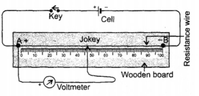
Assemble the potentiometer circuit as shown in the diagram. Close the key and record the corresponding potential difference by pressing the jockey on the potentiometer wire at regular 10 cm intervals. Repeat this process for six different wire lengths and tabulate the potential differences.
| Potential Difference (in volts) | \( V_1 \) | \( V_2 \) | \( V_3 \) | \( V_4 \) | \( V_5 \) | \( V_6 \) |
|---|---|---|---|---|---|---|
| Length (in cm) | \( l_1 \) | \( l_2 \) | \( l_3 \) | \( l_4 \) | \( l_5 \) | \( l_6 \) |
Calculate the ratio of potential difference to wire length. The experiment confirms that: \[ \frac{V_1}{l_1} = \frac{V_2}{l_2} = \frac{V_3}{l_3} = \frac{V_4}{l_4} = \frac{V_5}{l_5} = \frac{V_6}{l_6} = \text{constant} \] Since \( \frac{V}{l} = \text{constant} \), and the current (\( I \)) in a series circuit is constant, we have \( V \propto l \). Knowing that the length of the wire is directly proportional to its resistance (\( l \propto R \)), it follows that \( V \propto R \), or \( \frac{V}{R} = I \), which verifies Ohm's law.
In simple words: A potentiometer lets us measure potential differences across different lengths of a wire. Since resistance is proportional to length, showing that voltage is proportional to length proves that voltage is proportional to resistance, confirming Ohm's law.
Exam Tip: Use the proportional relationship \( V \propto l \) and \( l \propto R \) to establish the link to Ohm's law.
Question 6. What are ohmic resistances ? Given two examples.
Answer: Ohmic resistances are defined as conductors that strictly obey Ohm's law, maintaining a constant ratio of potential difference to current (\( \frac{V}{I} = R \)) across varying voltages.
Two examples: Copper (Cu), Aluminum (Al) (and all pure metals).
In simple words: Ohmic resistances are normal metal wires where doubling the voltage always doubles the current.
Exam Tip: Ohmic conductors produce a perfectly straight-line V-I graph passing through the origin.
Question 7. What are non-ohmic resistances ? Give two examples.
Answer: Non-ohmic resistances are electrical conductors or components whose resistance varies with current or voltage, meaning they do not follow Ohm's law.
Two examples: Semiconductor diodes (such as a diode valve) and a filament bulb.
In simple words: Non-ohmic resistances do not have a constant resistance. Devices like LED bulbs or diodes change their resistance depending on how much voltage is applied.
Exam Tip: A graph of V versus I for a non-ohmic conductor is a curve rather than a straight line.
Question 8. Derive an expression for three resistances connected in series.
Answer: Let three resistors with resistances \( R_1 \), \( R_2 \), and \( R_3 \) be joined end-to-end (in series) across a source of potential difference \( V \). Since they are connected in series, the same current \( I \) passes through each resistor. If the potential differences across \( R_1 \), \( R_2 \), and \( R_3 \) are \( V_1 \), \( V_2 \), and \( V_3 \) respectively, then by Ohm's law: \[ V_1 = I R_1 \] \[ V_2 = I R_2 \] \[ V_3 = I R_3 \] The total potential difference \( V \) across the entire combination is the sum of individual potential differences: \[ V = V_1 + V_2 + V_3 \] If \( R_s \) is the equivalent resistance of the series network, then: \[ V = I R_s \] Substituting the expressions for \( V_1, V_2, V_3 \) and \( V \): \[ I R_s = I R_1 + I R_2 + I R_3 \] Dividing both sides by the common current term \( I \), we get: \[ R_s = R_1 + R_2 + R_3 \] Thus, the equivalent resistance of resistors in series is the sum of their individual resistances.
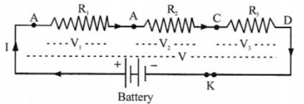
In simple words: When resistors are in series, the total resistance is found by simply adding up all the individual resistances. This happens because the current must pass through each resistor one after the other.
Exam Tip: Always state clearly that the current is identical through each resistor while the potential difference is divided.
Question 9. Derive an expression for three resistances connected in parallel.
Answer: Consider three resistors with resistances \( R_1 \), \( R_2 \), and \( R_3 \) connected in a parallel configuration across a common potential difference \( V \).
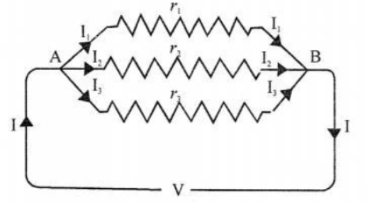
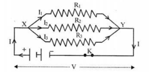
In a parallel circuit, the voltage across each resistor is the same, while the total current \( I \) from the battery splits into branch currents \( I_1 \), \( I_2 \), and \( I_3 \) flowing through \( R_1 \), \( R_2 \), and \( R_3 \) respectively: \[ I = I_1 + I_2 + I_3 \] By Ohm's law, the current through each individual branch is: \[ I_1 = \frac{V}{R_1} \] \[ I_2 = \frac{V}{R_2} \] \[ I_3 = \frac{V}{R_3} \] If \( R_p \) is the equivalent resistance of the parallel combination, the total current can be written as: \[ I = \frac{V}{R_p} \] Substituting these current relations into the total current equation: \[ \frac{V}{R_p} = \frac{V}{R_1} + \frac{V}{R_2} + \frac{V}{R_3} \] Dividing the entire equation by the common potential difference \( V \), we obtain the final equivalent expression: \[ \frac{1}{R_p} = \frac{1}{R_1} + \frac{1}{R_2} + \frac{1}{R_3} \] Hence, the reciprocal of the equivalent resistance for parallel resistors is equal to the sum of the reciprocals of the individual resistances.
In simple words: In a parallel connection, the total current is divided. Taking the reciprocal of the total resistance equals the sum of the reciprocals of all individual resistances, making the combined resistance smaller than any single resistor.
Exam Tip: Do not forget to take the reciprocal of your final calculated value to get the actual equivalent resistance \( R_p \).
Question 10. What do you understand by the term internal resistance of a cell ?
Answer: The internal resistance of a cell is defined as the resistive opposition offered by the electrolyte and electrodes inside the cell itself to the passage of electric current flowing through it.
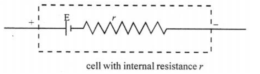
In simple words: Just like wires resist current, the chemicals and plates inside a battery also offer some resistance to the current flowing through them. This is called internal resistance.
Exam Tip: Internal resistance is denoted by lowercase \( r \) and causes a potential drop (\( Ir \)) when the cell is delivering current.
Question 11. State the factors on which internal resistance of a cell depends.
Answer: The internal resistance (\( r \)) of an electric cell is influenced by the following factors:
1. Surface Area of Electrodes: A larger electrode surface area in contact with the electrolyte decreases the internal resistance.
2. Distance between Electrodes: Increasing the separation distance between the plates increases the internal resistance.
3. Temperature: Raising the temperature (\( T \)) of the electrolyte decreases its viscosity and increases ion mobility, thereby lowering internal resistance (\( r \propto \frac{1}{T} \)).
4. Concentration: A higher concentration of the electrolyte results in greater internal resistance due to increased inter-ionic collisions.
In simple words: Internal resistance is lower if the battery plates are larger, closer together, or hotter, but is higher if the chemical solution inside is highly concentrated.
Exam Tip: Remember that as a cell gets older, its internal resistance increases significantly due to chemical degradation.
Question 12. What is the difference between emf and terminal voltage of a cell ?
Answer: The differences between electromotive force (e.m.f.) and terminal voltage of a cell are specified below:
- Electromotive Force (e.m.f., \( E \)): The potential difference measured between the terminals of a cell when no current is being drawn from it (i.e., when the circuit is open). It is a characteristic property of the cell's chemicals.
- Terminal Voltage (\( V \)): The potential difference measured across the terminals of a cell when current is being drawn from it (i.e., when the circuit is closed). It is always less than the e.m.f. due to the internal potential drop (\( V = E - Ir \)).
In simple words: EMF is the full voltage of a battery when it is not being used. Terminal voltage is the actual voltage you measure across its terminals when it is connected to a working circuit and current is flowing.
Exam Tip: The relation \( V = E - Ir \) is vital; note that \( V < E \) when the cell is discharging, and \( V = E \) only when the circuit is open.
Multiple Choice Questions
Question 1. In a series circuit: (a) p.d. across all resistors is same (b) current flowing through all resistors is same (c) The combined resistance of all resistors is less than individual resistors. (d) none of the above
Answer: (b) current flowing through all resistors is same
In simple words: Since there is only a single path for charge carriers to travel, the rate of current flow remains identical through every component in a series loop.
Exam Tip: Total resistance in a series circuit is calculated as \( R_s = R_1 + R_2 + R_3 + \dots \), which is why the combined value is always greater than any single resistor.
Question 2. In a parallel circuit: (a) p.d. across all resistors is same (b) current flowing through all resistors is same (c) the equivalent resistance of all resistors is more than any of the individual resistors (d) none of the above
Answer: (a) p.d. across all resistors is same
In simple words: In a parallel arrangement, each resistor is connected directly across the same main terminals, ensuring they all experience the same potential difference.
Exam Tip: In a parallel circuit, current splits into different branches depending on each branch's resistance, while potential difference stays constant.
Question 3. Two resistors of 2 Ω. each are connected in a parallel. The equivalent resistance is : (a) less than 2 Ω but more than 1Ω (b) one ohm (c) four ohm (d) between 4 Ω and 2 Ω
Answer: (b) one ohm
In simple words: Using the parallel resistance formula, \( \frac{1}{R} = \frac{1}{2} + \frac{1}{2} = 1 \), which gives an equivalent resistance of exactly \( 1\text{ }\Omega \).
Exam Tip: When \( N \) identical resistors each of resistance \( R \) are connected in parallel, the equivalent resistance is simply \( \frac{R}{N} \).
Question 4. A new cell is marked 1.5 V. When connected to an external resistance, the voltmeter connected to its terminals reads 1.2 V. The drop in potential across the terminals of the cell is due to the : (a) internal resistance of cell (b) external resistance . (c) both (a) and (b) (d)none of these
Answer: (a) internal resistance of cell
In simple words: The lost potential difference (potential drop of 0.3 V) is spent overcoming the resistance within the electrolyte of the cell.
Exam Tip: The potential drop is given by \( v = E - V \). In this case, \( v = 1.5 - 1.2 = 0.3 \text{ V} \), which is equal to \( I \cdot r \).
Question 5. A potentiometer is connected to a cell through switch in series. To one end of the potentiometer is attached a voltmeter with the help of connecting wire and a jockey. When the jockey is moved over the potentiometer wire from zero end to 100 cm the reading shown by voltmeter is likely to : (a) decrease (b) increase (c) does not change (d) none of these
Answer: (b) increase
In simple words: As the jockey is moved farther along the wire, the length of the wire segment in the voltmeter circuit increases. Since potential difference is directly proportional to length, the voltmeter reading rises.
Exam Tip: The potentiometer works on the principle that the potential drop across any portion of the wire is directly proportional to its length (\( V \propto l \)).
Question 6. When the current is drawn from a cell in a closed circuit, the potential difference between the terminals of cell is called : (a) e.m.f. (b) p.d. (c) terminal voltage (d) both (a) and (b)
Answer: (c) terminal voltage
In simple words: Terminal voltage is specifically the electrical potential difference across the battery ends while current is actually circulating.
Exam Tip: The term electromotive force (e.m.f.) is only used when the circuit is open and no current flows.
Numerical Problems on Resistance
Practice Problems - 1
Question 1. Calculate the equivalent resistance
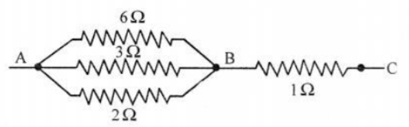
1. between points A and B
2. between points A and C.
Answer: 1. Equivalent resistance between points A and B:
The three resistors \( 6\text{ }\Omega \), \( 3\text{ }\Omega \), and \( 2\text{ }\Omega \) are connected in parallel between terminals A and B. Their combined resistance (\( R_{AB} \)) is: \[ \frac{1}{R_{AB}} = \frac{1}{6} + \frac{1}{3} + \frac{1}{2} = \frac{1 + 2 + 3}{6} = \frac{6}{6} = 1 \] \[ R_{AB} = 1\text{ }\Omega \] 2. Equivalent resistance between points A and C:
The parallel combination \( R_{AB} \) is in series with the \( 1\text{ }\Omega \) resistor (\( R_{BC} \)) located between B and C. Therefore: \[ R_{AC} = R_{AB} + R_{BC} = 1 + 1 = 2\text{ }\Omega \] In simple words: The parallel network between A and B simplifies to a single \( 1\text{ }\Omega \) resistor. Adding the remaining \( 1\text{ }\Omega \) resistor in series gives a total of \( 2\text{ }\Omega \) across the whole circuit.
Exam Tip: Always solve the parallel branches first to simplify the network before adding series components.
Question 2. In figure, calculate equivalent resistance between points
1. A and B
2. B and C
3. A and C.
Answer:
1. Equivalent resistance between A and B (\( R_1 \)):
The resistors \( 4\ \Omega \) and \( 12\ \Omega \) are connected in parallel.
\( \frac{1}{R_1} = \frac{1}{4} + \frac{1}{12} = \frac{3+1}{12} = \frac{4}{12} = \frac{1}{3} \)
\( R_1 = 3\ \Omega \)
2. Equivalent resistance between B and C (\( R_2 \)):
The resistors \( 12\ \Omega \), \( 24\ \Omega \), and \( 8\ \Omega \) are in parallel.
\( \frac{1}{R_2} = \frac{1}{12} + \frac{1}{24} + \frac{1}{8} = \frac{2+1+3}{24} = \frac{6}{24} = \frac{1}{4} \)
\( R_2 = 4\ \Omega \)
3. Equivalent resistance between A and C (\( R \)):
Since the sections AB and BC are connected in series:
\( R = R_1 + R_2 = 3\ \Omega + 4\ \Omega = 7\ \Omega \)
In simple words: 1. The parallel combination between A and B has a resistance of 3 ohms. 2. The parallel combination between B and C has a resistance of 4 ohms. 3. Adding these two sections in series gives a total resistance of 7 ohms.
Exam Tip: Work out each parallel branch group independently before adding their equivalent values together in series.
Practice Problems : 2
Question 1. Calculate the equivalent resistance between points
1. B and E (ii) A and F.
Answer:
1. Equivalent resistance between B and E:
The outer circuit branch consisting of C, D, and E contains three series resistors: \( 1\ \Omega \), \( 2\ \Omega \), and \( 3\ \Omega \).
Equivalent resistance of this path, \( R_{\text{outer}} = 1 + 2 + 3 = 6\ \Omega \)
This combination is in parallel with the direct \( 3\ \Omega \) resistor between B and E.
\( \frac{1}{R_{BE}} = \frac{1}{R_{\text{outer}}} + \frac{1}{3} = \frac{1}{6} + \frac{1}{3} = \frac{1+2}{6} = \frac{3}{6} = \frac{1}{2} \)
\( R_{BE} = 2\ \Omega \)
2. Equivalent resistance between A and F:
The resistances along the main line (the \( 3\ \Omega \) resistor between A and B, the equivalent resistance \( R_{BE} = 2\ \Omega \), and the \( 3\ \Omega \) resistor between E and F) are connected in series.
\( R_{AF} = 3\ \Omega + R_{BE} + 3\ \Omega = 3 + 2 + 3 = 8\ \Omega \)
In simple words: 1. The loop on the right acts as a 6-ohm path in parallel with a 3-ohm path, which simplifies to 2 ohms between B and E. 2. To find the total resistance between A and F, we add the 3-ohm inlet, this 2-ohm middle section, and the 3-ohm outlet in series, giving 8 ohms.
Exam Tip: Identify the closed loops first to reduce complex network branches step-by-step into equivalent series elements.
Question 2. Calculate the equivalent resistance of circuit diagram shown in Fig. below.
Answer:
First, identify the series paths in the top and bottom branches:
1. Upper path contains resistors A and B in series:
\( R_{\text{top}} = A + B = 4\ \Omega + 8\ \Omega = 12\ \Omega \)
2. Lower path contains resistors C and D in series:
\( R_{\text{bottom}} = C + D = 1.5\ \Omega + 4.5\ \Omega = 6\ \Omega \)
The total network consists of three parallel branches: \( R_{\text{top}} = 12\ \Omega \), \( E = 3\ \Omega \), and \( R_{\text{bottom}} = 6\ \Omega \).
\( \frac{1}{R} = \frac{1}{R_{\text{top}}} + \frac{1}{E} + \frac{1}{R_{\text{bottom}}} \)
\( \frac{1}{R} = \frac{1}{12} + \frac{1}{3} + \frac{1}{6} = \frac{1 + 4 + 2}{12} = \frac{7}{12} \)
\( R = \frac{12}{7} \approx 1.71\ \Omega \)
In simple words: The top branch has a combined resistance of 12 ohms, and the bottom has 6 ohms. Combining these three parallel branches (12, 3, and 6 ohms) results in a total equivalent resistance of approximately 1.71 ohms.
Exam Tip: Simplify the series components inside parallel loops first to reduce the network to a simple multi-branch parallel calculation.
Practice Problems : 3
Question 1. Equivalent resistance of circuit diagram is 6Ω. Calculate the value of x.
Answer:
First, find the total resistance of the series elements in each branch:
1. Upper branch contains three series resistors: \( 8\ \Omega \), \( 9\ \Omega \), and \( x\ \Omega \).
\( R_1 = 8 + 9 + x = 17 + x \)
2. Lower branch contains two series resistors: \( 3\ \Omega \) and \( 5\ \Omega \).
\( R_2 = 3 + 5 = 8\ \Omega \)
Given total equivalent resistance of this parallel combination is \( R = 6\ \Omega \).
\( \frac{1}{R} = \frac{1}{R_1} + \frac{1}{R_2} \point \)
\( \frac{1}{6} = \frac{1}{17+x} + \frac{1}{8} \)
\( \frac{1}{17+x} = \frac{1}{6} - \frac{1}{8} \)
\( \frac{1}{17+x} = \frac{4 - 3}{24} = \frac{1}{24} \)
\( 17 + x = 24 \)
\( x = 24 - 17 = 7\ \Omega \)
In simple words: The lower branch has a resistance of 8 ohms. Setting up the parallel combination equation with the total resistance of 6 ohms reveals that the upper branch must be 24 ohms. Subtracting 17 ohms from this gives the value of x as 7 ohms.
Exam Tip: Show the common denominator step clearly when solving fractional algebraic equations like \( \frac{1}{6} - \frac{1}{8} \).
Question 2. Equivalent resistance of circuit diagram is 5Ω. Calculate the value of x.
Answer:
The circuit is composed of a \( 4\ \Omega \) resistor connected in series with a parallel network between points B and C.
Given the total equivalent resistance of the entire circuit is \( R = 5\ \Omega \).
Resistance of the parallel combination section, \( R_p \):
\( R_p = 5\ \Omega - 4\ \Omega = 1\ \Omega \)
The parallel combination consists of three branches: \( 6\ \Omega \), \( x\ \Omega \), and \( 2\ \Omega \).
\( \frac{1}{R_p} = \frac{1}{6} + \frac{1}{2} + \frac{1}{x} \)
\( \frac{1}{1} = \frac{1 + 3}{6} + \frac{1}{x} \)
\( 1 = \frac{4}{6} + \frac{1}{x} \)
\( 1 = \frac{2}{3} + \frac{1}{x} \)
\( \frac{1}{x} = 1 - \frac{2}{3} = \frac{1}{3} \)
\( x = 3\ \Omega \)
In simple words: Since the total resistance is 5 ohms and the first resistor is 4 ohms, the parallel section must have a resistance of 1 ohm. Working out the parallel formula shows that x must equal 3 ohms.
Exam Tip: Subtract the series resistor first to isolate the parallel branch math, keeping your algebraic steps simple and clean.
Numerical Problems on Ohm’s Law
Practice Problems : 1
Question 1. A current of 0.2 A flows through a conductor of resistance 4.50. Calculate p.d. at the ends of conductor.
Answer: Given data:
Current, \( I = 0.2\text{ A} \)
Resistance, \( R = 4.5\ \Omega \)
Using Ohm's Law:
\( V = I \cdot R \)
\( V = 0.2\text{ A} \times 4.5\ \Omega = 0.9\text{ V} \)
In simple words: Multiplying the current of 0.2 Amperes by the resistance of 4.5 ohms gives a voltage drop of 0.9 Volts.
Exam Tip: Be sure to write the correct SI unit, Volt (V), for the calculated potential difference.
Question 2. A bulb of resistance 4000 is connected to 200 V mains. Calculate the magnitude of current.
Answer: Given data:
Resistance of the bulb, \( R = 400\ \Omega \) (per the textbook calculation parameters)
Potential difference, \( V = 200\text{ V} \)
Using Ohm's Law:
\( I = \frac{V}{R} \)
\( I = \frac{200}{400} = 0.5\text{ A} \)
In simple words: Dividing the voltage of 200 Volts by the bulb's resistance of 400 ohms gives a current of 0.5 Amperes.
Exam Tip: Always make sure to write down the final current in Amperes, clearly showing the fraction simplification.
Question 3. An electric heater draws a current of 5 A, when connected to 220 V mains. Calculate the resistance of its filament.
Answer: Given data:
Current, \( I = 5\text{ A} \)
Voltage, \( V = 220\text{ V} \)
According to Ohm's Law:
\( R = \frac{V}{I} \)
\( R = \frac{220}{5} = 44\ \Omega \)
In simple words: Dividing the voltage of 220 Volts by the current of 5 Amperes gives the filament resistance as 44 ohms.
Exam Tip: Standard heater filaments have low resistance to draw higher current and generate sufficient heat; always check that your numerical values reflect this.
Practice Problems : 2
Question 1. Four resistors of resistance 0.5 Ω, 1.5Ω, 4Ω and 6Ω are connected in series to a battery of e.m.f. 6 V and negligible internal resistance. Calculate :
1. current drawn from the cell
2. p.d. at the ends of each resistor.
Answer:
First, find the total resistance of the series circuit:
\( R_s = 0.5\ \Omega + 1.5\ \Omega + 4\ \Omega + 6\ \Omega = 12\ \Omega \)
Given EMF, \( V = 6\text{ V} \)
1. Current drawn from the cell:
\( I = \frac{V}{R_s} = \frac{6}{12} = 0.5\text{ A} \)
2. Potential difference across the ends of each resistor:
\( V_1 = I \cdot R_1 = 0.5 \times 0.5 = 0.25\text{ V} \)
\( V_2 = I \cdot R_2 = 0.5 \times 1.5 = 0.75\text{ V} \)
\( V_3 = I \cdot R_3 = 0.5 \times 4 = 2\text{ V} \)
\( V_4 = I \cdot R_4 = 0.5 \times 6 = 3\text{ V} \)
In simple words: 1. The total resistance in the circuit is 12 ohms, which draws a current of 0.5 Amperes from the 6V battery. 2. The voltage drop across each resistor is 0.25V, 0.75V, 2V, and 3V respectively.
Exam Tip: Check that the sum of the individual voltage drops (\( 0.25 + 0.75 + 2 + 3 = 6\text{ V} \)) matches the total battery EMF to verify your calculations.
Question 2. Figure shows a circuit diagram having a battery of 24 V and negligible internal resistance. Calculate :
1. reading of the ammeter,
2. reading of V1, V2 and V3.
Answer:
First, find the equivalent parallel resistance (\( R_p \)) of the \( 6\ \Omega \) and \( 3\ \Omega \) resistors:
\( \frac{1}{R_p} = \frac{1}{6} + \frac{1}{3} = \frac{1+2}{6} = \frac{3}{6} = \frac{1}{2} \)
\( R_p = 2\ \Omega \point \)
Calculate total circuit resistance:
\( R_{\text{total}} = 1.5\ \Omega + R_p + 8.5\ \Omega = 1.5 + 2 + 8.5 = 12\ \Omega \)
1. Reading of the ammeter (current \( I \)):
\( I = \frac{V}{R_{\text{total}}} = \frac{24\text{ V}}{12\ \Omega} = 2\text{ A} \)
2. Reading of the voltmeters:
\( V_1 = I \cdot 1.5 = 2\text{ A} \times 1.5\ \Omega = 3\text{ V} \)
\( V_2 = I \cdot R_p = 2\text{ A} \times 2\ \Omega = 4\text{ V} \)
\( V_3 = I \cdot 8.5 = 2\text{ A} \times 8.5\ \Omega = 17\text{ V} \point \)
In simple words: 1. The ammeter reads a current of 2 Amperes. 2. The three voltmeters show voltage drops of 3 Volts, 4 Volts, and 17 Volts respectively.
Exam Tip: Remember that the reading of voltmeter \( V_2 \) across the parallel branch is calculated using the equivalent parallel resistance \( R_p \).
Practice Problems : 3
Question 1. Three resistors of 6Ω, 2Ω and x are connected in series to a cell of e.m.f 3/2 V, when the current registered in circuit is 1/6 A. Draw the circuit diagram and calculate value of x
Answer:
Given data:
Cell EMF, \( V = \frac{3}{2}\text{ V} \)
Circuit current, \( I = \frac{1}{6}\text{ A} \)
Calculate the total resistance of the series circuit using Ohm's Law:
\( R_{\text{total}} = \frac{V}{I} = \frac{\frac{3}{2}}{\frac{1}{6}} = \frac{3}{2} \times 6 = 9\ \Omega \)
Since the resistors are connected in series:
\( R_1 + R_2 + x = R_{\text{total}} \)
\( 6\ \Omega + 2\ \Omega + x = 9\ \Omega \point \)
\( 8 + x = 9 \)
\( x = 1\ \Omega \)
In simple words: The circuit diagram is drawn above with three series resistors. The total circuit resistance must be 9 ohms, which means the unknown resistor x is equal to 1 ohm.
Exam Tip: Be sure to include the ammeter "A" in your circuit diagram as specified by the question requirements.
Question 2. Carefully study the circuit diagram in figure and calculate the value of resistor x.
Answer:
First, compute the equivalent resistance of the three parallel branches \( R_1 \):
\( \frac{1}{R_1} = \frac{1}{12} + \frac{1}{6} + \frac{1}{3} = \frac{1+2+4}{12} = \frac{7}{12} \)
\( R_1 = \frac{12}{7}\ \Omega \approx 1.71\ \Omega \)
Given total battery voltage \( V = 6\text{ V} \), and the circuit current \( I = 0.4\text{ A} \).
The total resistance of the series-parallel combination is:
\( R_{\text{total}} = \frac{V}{I} = \frac{6}{0.4} = 15\ \Omega \)
The circuit contains the \( 2\ \Omega \) resistor, the parallel combination \( R_1 \), and the resistor \( x \) in series:
\( 2 + R_1 + x = 15 \)
\( 2 + 1.71 + x = 15 \)
\( 3.71 + x = 15 \point \)
\( x = 15 - 3.71 = 11.29\ \Omega \)
In simple words: The parallel section simplifies to about 1.71 ohms. The total circuit resistance must be 15 ohms to let 0.4 Amperes flow. Subtracting 2 ohms and 1.71 ohms from 15 ohms leaves x equal to 11.29 ohms.
Exam Tip: Write down intermediate parallel resistance fractions like \( \frac{12}{7} \) to maintain numerical precision before subtracting at the end.
Practice Problems : 4
Question 1. Three resistors of 4Ω, 6Ω. and 12Ω are connected in parallel The combination of these resistors is connected in series to a resistance of 2Ω and then to a battery of e.m.f 6 V and negligible internal resistance.
(a) Draw the circuit diagram
(b) Calculate the current in main circuit
(c) Calculate the current in each of the resistors in parallel
Answer:
(a) The circuit diagram is represented below:
(b) Calculate the current in main circuit:
Find the equivalent parallel resistance of \( 4\ \Omega \), \( 6\ \Omega \), and \( 12\ \Omega \), \( R_1 \):
\( \frac{1}{R_1} = \frac{1}{4} + \frac{1}{6} + \frac{1}{12} = \frac{3+2+1}{12} = \frac{6}{12} = \frac{1}{2} \)
\( R_1 = 2\ \Omega \)
Total resistance of the circuit with the series \( 2\ \Omega \) resistor:
\( R_{\text{total}} = R_1 + 2\ \Omega = 2 + 2 = 4\ \Omega \)
The current in the main circuit is:
\( I = \frac{V}{R_{\text{total}}} = \frac{6}{4} = 1.5\text{ A} \point \)
(c) Calculate the current in each of the resistors in parallel:
Potential difference across the parallel combination AB:
\( V_{AB} = I \cdot R_1 = 1.5\text{ A} \times 2\ \Omega = 3\text{ V} \)
Using \( I = \frac{V_{AB}}{R} \), the current through each parallel resistor is:
\( I_{\text{1}} \text{ through } 4\ \Omega = \frac{3}{4} = 0.75\text{ A} \)
\( I_{\text{2}} \text{ through } 6\ \Omega = \frac{3}{6} = 0.5\text{ A} \)
\( I_{\text{3}} \text{ through } 12\ \Omega = \frac{3}{12} = 0.25\text{ A} \)
In simple words: (a) The circuit diagram is drawn above. (b) The total circuit resistance is 4 ohms, drawing a main current of 1.5 Amperes. (c) The voltage across the parallel group is 3 Volts, which splits the current into 0.75A, 0.5A, and 0.25A respectively.
Exam Tip: When dividing current in parallel branches, verify that the sum of the branch currents (\( 0.75 + 0.5 + 0.25 = 1.5\text{ A} \)) matches the main current.
Question 2. Study the circuit diagram in figure carefully and calculate:
(a) current in main circuit
(b) current in each of the resistors in parallel circuit.
Answer:
First, find the equivalent resistance of each of the two parallel sections, AB and BC:
1. For section AB consisting of \( 1.5\ \Omega \) and \( 3\ \Omega \) in parallel (labeled \( R_1 \)):
\( \frac{1}{R_1} = \frac{1}{1.5} + \frac{1}{3} = \frac{2}{3} + \frac{1}{3} = \frac{3}{3} = 1 \implies R_1 = 1\ \Omega \)
2. For section BC consisting of \( 6\ \Omega \) and \( 12\ \Omega \) in parallel (labeled \( R_2 \)):
\( \frac{1}{R_2} = \frac{1}{6} + \frac{1}{12} = \frac{2+1}{12} = \frac{3}{12} = \frac{1}{4} \implies R_2 = 4\ \Omega \)
Total circuit resistance:
\( R_{\text{total}} = R_1 + R_2 = 1\ \Omega + 4\ \Omega = 5\ \Omega \)
(a) Current in main circuit:
\( I = \frac{V}{R_{\text{total}}} = \frac{9\text{ V}}{5\ \Omega} = 1.8\text{ A} \)
(b) Current in each parallel resistor:
- P.d. across parallel section AB:
\( V_1 = I \cdot R_1 = 1.8\text{ A} \times 1\ \Omega = 1.8\text{ V} \)
- Current in \( 1.5\ \Omega \) resistor: \( I_{\text{1.5}} = \frac{1.8}{1.5} = 1.2\text{ A} \)
- Current in \( 3\ \Omega \) resistor: \( I_{\text{3}} = \frac{1.8}{3} = 0.6\text{ A} \)
- P.d. across parallel section BC:
\( V_2 = I \cdot R_2 = 1.8\text{ A} \times 4\ \Omega = 7.2\text{ V} \)
- Current in \( 6\ \Omega \) resistor: \( I_{\text{6}} = \frac{7.2}{6} = 1.2\text{ A} \)
- Current in \( 12\ \Omega \) resistor: \( I_{\text{12}} = \frac{7.2}{12} = 0.6\text{ A} \)
In simple words: (a) The equivalent resistance is 5 ohms, drawing a total current of 1.8 Amperes. (b) The voltage drops are 1.8V and 7.2V. These split currents to 1.2A and 0.6A across the first section, and 1.2A and 0.6A across the second section.
Exam Tip: Calculate the individual voltage drops across each parallel group before using Ohm's law to solve for the specific branch currents.
Practice Problems : 5
Question 1. Figure shows a circuit diagram containing 12 cells, each of e.m.f 1.5 V and intenal resistance 0.25Ω Calculate:
(a) Total internal resistance
(b) Total e.m.f.
(c) Total external resistance
(d) Reading shown by the ammeter
(e) Current in 12Ω and 8Ω resistors
(f) p.d. across 2.2 resistor
(g) Drop in potential across the terminals of the cell
Answer:
Given parameters:
Number of series cells, \( n = 12 \)
EMF of each cell \( = 1.5\text{ V} \)
Internal resistance per cell \( = 0.25\ \Omega \)
Ammeter resistance \( = 0.8\ \Omega \)
(a) Total internal resistance of the battery:
\( r_{\text{total}} = n \cdot r = 12 \times 0.25\ \Omega = 3\ \Omega \)
(b) Total electromotive force (e.m.f.):
\( E_{\text{total}} = n \cdot E = 12 \times 1.5\text{ V} = 18\text{ V} \)
(c) Total external resistance:
The parallel combination has two branches:
Upper branch resistance \( = 4\ \Omega + 8\ \Omega = 12\ \Omega \)
Lower branch resistance \( = 12\ \Omega \)
Equivalent resistance of this parallel section, \( R_p \):
\( R_p = \frac{12 \times 12}{12 + 12} = 6\ \Omega \point \)
Including the series ammeter and the \( 2.2\ \Omega \) resistor:
\( R_{\text{external}} = 0.8\ \Omega + 6\ \Omega + 2.2\ \Omega = 9\ \Omega \)
(d) Reading shown by the ammeter:
Total resistance of the circuit:
\( R_{\text{total}} = R_{\text{external}} + r_{\text{total}} = 9 + 3 = 12\ \Omega \)
Main current flowing in the circuit:
\( I = \frac{E_{\text{total}}}{R_{\text{total}}} = \frac{18\text{ V}}{12\ \Omega} = 1.5\text{ A} \)
(e) Current in \( 12\ \Omega \) and \( 8\ \Omega \) resistors:
Since the parallel combination consists of two branches with equal resistance (\( 12\ \Omega \) each), the main current of \( 1.5\text{ A} \) divides equally between them:
\( I_{\text{branch}} = \frac{1.5}{2} = 0.75\text{ A} \)
Thus, the current through both the \( 12\ \Omega \) and the \( 8\ \Omega \) resistor is **0.75 A**.
(f) Potential difference across the \( 2.2\ \Omega \) resistor:
\( V = I \cdot R = 1.5\text{ A} \times 2.2\ \Omega = 3.3\text{ V} \)
(g) Drop in potential across the terminals of the cell (internal voltage drop):
\( v_{\text{lost}} = I \cdot r_{\text{total}} = 1.5\text{ A} \times 3\ \Omega = 4.5\text{ V} \)
Therefore, the terminal voltage is:
\( V_{\text{terminal}} = E_{\text{total}} - v_{\text{lost}} = 18 - 4.5 = 13.5\text{ V} \)
In simple words: (a) The combined internal resistance is 3 ohms. (b) The total voltage of the 12 cells is 18 Volts. (c) The total external circuit resistance is 9 ohms. (d) The main current through the ammeter is 1.5 Amperes. (e) The current splits equally into 0.75 Amperes in each of the parallel paths. (f) The voltage drop across the 2.2-ohm resistor is 3.3 Volts. (g) The internal potential drop is 4.5 Volts, leaving 13.5 Volts across the terminal ends.
Exam Tip: Always make sure to include the ammeter's internal resistance as part of the total external resistance of the circuit loop.
Question 2. Four cells, each of e.m.f 2 V and internal resistance 0.2 Ω each are connected in series to form a battery. This battery is connected to an ammeter, a resistance 1.2 and then to a set of resistance of 4 Ω, 6 Ω and 12 Ω in parallel to complete the overall circuit in series.
(a) Draw circuit diagram of arangment.
(b) Calculate total internal resistance
(c) Total e.m.f.
(d) Current recorded by ammeter.
(e) Current flowing through 6 wire in parallel.
(f) Drop in potential across the terminals of the battery.
Answer:
(a) The circuit diagram is represented below:
(b) Total internal resistance of the 4 series cells:
\( r_{\text{total}} = 4 \times 0.2\ \Omega = 0.8\ \Omega \)
(c) Total electromotive force (e.m.f.):
\( E_{\text{total}} = 4 \times 2\text{ V} = 8\text{ V} \)
(d) Current recorded by ammeter:
Find the equivalent resistance of the parallel combination, \( R_p \):
\( \frac{1}{R_p} = \frac{1}{4} + \frac{1}{6} + \frac{1}{12} = \frac{3+2+1}{12} = \frac{6}{12} = \frac{1}{2} \implies R_p = 2\ \Omega \)
Total resistance of the circuit:
\( R_{\text{total}} = 1.2\ \Omega\ (\text{series}) + 2\ \Omega\ (R_p) + 0.8\ \Omega\ (\text{internal}) = 4\ \Omega \)
Current recorded by ammeter:
\( I = \frac{E_{\text{total}}}{R_{\text{total}}} = \frac{8\text{ V}}{4\ \Omega} = 2\text{ A} \)
(e) Current flowing through the \( 6\ \Omega \) resistor:
Voltage drop across the parallel network:
\( V_p = I \cdot R_p = 2\text{ A} \times 2\ \Omega = 4\text{ V} \)
Current through the \( 6\ \Omega \) resistor:
\( I_6 = \frac{V_p}{6} = \frac{4}{6} \approx 0.67\text{ A} \)
(f) Drop in potential across the terminals of the battery:
\( v_{\text{drop}} = I \cdot r_{\text{total}} = 2\text{ A} \times 0.8\ \Omega = 1.6\text{ V} \)
Therefore, the terminal potential difference across the battery ends is:
\( V_{\text{terminal}} = E_{\text{total}} - v_{\text{drop}} = 8 - 1.6 = 6.4\text{ V} \)
In simple words: (a) The circuit diagram is represented above. (b) The total internal resistance is 0.8 ohms. (c) Total battery voltage is 8 Volts. (d) The ammeter reads a current of 2 Amperes. (e) The current passing through the 6-ohm branch is about 0.67 Amperes. (f) The potential drop inside the battery is 1.6 Volts.
Exam Tip: Be sure to distinguish between "emf" (8V), "terminal voltage" (6.4V), and "internal drop" (1.6V) when writing out your steps.
Practice Problems : 6
Question 1. Two cells, each of e.m.f 1.5 V and internal resistance 1 Ω are connected in parallel, to form a battery. The battery is connected to an externari resistance of 0.5 Ω and two resistances of 3 Ω and 1.5 Ω in parallel.
(a) Draw the circuit diagram.
(b) Calculate the current in main circuit.
(c) Calculate the current in 1.5 Ω resistor.
(d) Calculate the drop in potential across the terminal of the battery.
Answer:
(a) The circuit diagram is represented below:
(b) Calculate the current in main circuit:
Equivalent internal resistance of two parallel cells (\( r_p \)):
\( \frac{1}{r_p} = \frac{1}{1} + \frac{1}{1} = 2 \implies r_p = 0.5\ \Omega \)
Equivalent resistance of the external parallel resistors (\( R_p \)):
\( \frac{1}{R_p} = \frac{1}{3} + \frac{1}{1.5} = \frac{1 + 2}{3} = \frac{3}{3} = 1 \implies R_p = 1\ \Omega \)
Total resistance of the circuit:
\( R_{\text{total}} = R_p + 0.5\ \Omega\ (\text{series}) + r_p = 1 + 0.5 + 0.5 = 2\ \Omega \)
Current in the main circuit:
\( I = \frac{E}{R_{\text{total}}} = \frac{1.5\text{ V}}{2\ \Omega} = 0.75\text{ A} \)
(c) Calculate the current in \( 1.5\ \Omega \) resistor:
Voltage drop across parallel group PQ:
\( V_{PQ} = I \cdot R_p = 0.75\text{ A} \times 1\ \Omega = 0.75\text{ V} \)
Current through the \( 1.5\ \Omega \) resistor:
\( I_1 = \frac{V_{PQ}}{1.5} = \frac{0.75}{1.5} = 0.5\text{ A} \point \)
(d) Calculate the drop in potential across the terminal of the battery:
\( v_{\text{drop}} = I \cdot r_p = 0.75\text{ A} \times 0.5\ \Omega = 0.375\text{ V} \)
In simple words: (a) The circuit diagram is represented above. (b) The total circuit resistance is 2 ohms, giving a main current of 0.75 Amperes. (c) The current flowing through the 1.5-ohm resistor is 0.5 Amperes. (d) The internal potential drop is 0.375 Volts.
Exam Tip: Recall that for cells in parallel, the total EMF is equal to the EMF of a single cell (1.5 V), not the sum of the cells.
Question 2. Four cells, each of e.m.f. 1.5 V and internal resistance 2 Ω. each are connected in parallel to form a battery. The battery is connected to an external resistance of 0.5 Ω. and three resistances of 12 Ω, 6 Ω and 4 Ω. in parallel.
1. Draw the circuit diagram.
2. Calculate current in main circuit
3. Calculate current in 4 D resistor.
4. Calculate drop in potential across the terminals of battery.
Answer:
1. The circuit diagram is represented below:
2. Calculate current in main circuit:
Equivalent resistance of the external parallel combination (\( R_p \)):
\( \frac{1}{R_p} = \frac{1}{12} + \frac{1}{6} + \frac{1}{4} = \frac{1+2+3}{12} = \frac{6}{12} = \frac{1}{2} \implies R_p = 2\ \Omega \)
Equivalent internal resistance of the 4 parallel cells (\( r_p \)):
\( \frac{1}{r_p} = \frac{1}{2} + \frac{1}{2} + \frac{1}{2} + \frac{1}{2} = \frac{4}{2} = 2 \implies r_p = 0.5\ \Omega \)
Total resistance of the circuit:
\( R_{\text{total}} = R_p + r_p + 0.5\ \Omega\ (\text{series}) = 2 + 0.5 + 0.5 = 3\ \Omega \)
Total EMF of parallel combination \( E = 1.5\text{ V} \)
Current in the main circuit:
\( I = \frac{E}{R_{\text{total}}} = \frac{1.5\text{ V}}{3\ \Omega} = 0.5\text{ A} \)
3. Calculate current in \( 4\ \Omega \) resistor:
Potential difference across parallel network PQ:
\( V_{PQ} = I \cdot R_p = 0.5\text{ A} \times 2\ \Omega = 1\text{ V} \point \)
Current through the \( 4\ \Omega \) resistor:
\( I_4 = \frac{V_{PQ}}{4} = \frac{1}{4} = 0.25\text{ A} \)
4. Calculate drop in potential across the terminals of battery:
\( v_{\text{drop}} = I \cdot r_p = 0.5\text{ A} \times 0.5\ \Omega = 0.25\text{ V} \)
In simple words: 1. The diagram shows the 4 parallel cells and parallel load resistors. 2. The total resistance of the circuit is 3 ohms, yielding a main current of 0.5 Amperes. 3. The current through the 4-ohm resistor is 0.25 Amperes. 4. The potential drop inside the battery is 0.25 Volts.
Exam Tip: Be sure to write out the individual steps for finding both the parallel external equivalent and the parallel internal equivalent separately.
Practice Problems : 7
Question 1. A cell of e.m.f 1.5 V, records a p.d. of 1.35 V, when connected lo an external resistance R, such that current flowing through circuit is 0.75 A. Calculate the value of R and internal resistance of cell
Answer: Given data:
EMF of cell, \( E = 1.5\text{ V} \)
Terminal potential difference, \( V = 1.35\text{ V} \)
Circuit current, \( I = 0.75\text{ A} \)
Using Ohm's Law to find external resistance \( R \):
\( R = \frac{V}{I} = \frac{1.35\text{ V}}{0.75\text{ A}} = 1.8\ \Omega \)
Calculating the internal resistance \( r \):
\( E - V = I \cdot r \)
\( 1.5 - 1.35 = 0.75 \times r \)
\( 0.15 = 0.75 \times r \)
\( r = \frac{0.15}{0.75} = 0.2\ \Omega \)
In simple words: The external load resistance is found to be 1.8 ohms. Using the potential difference drop, the internal resistance of the cell is calculated as 0.2 ohms.
Exam Tip: Use the relation \( E - V = Ir \) as a quick and reliable shortcut to find the internal resistance when both EMF and terminal voltage are provided.
Question 2. In figure a current of 1 A flows through the circuit, when p.d. recorded at the ends of parallel resistors is 1 volt. Calculate the value of R and r.
Answer:
Given data:
Total current, \( I = 1\text{ A} \)
Voltage across parallel combination, \( V = 1\text{ V} \)
Cell EMF, \( E = 1.5\text{ V} \)
The current through the \( 3\ \Omega \) resistor is:
\( I_1 = \frac{V}{3} = \frac{1}{3}\text{ A} \)
The current through the unknown parallel resistor \( R \) is:
\( I_2 = I - I_1 = 1 - \frac{1}{3} = \frac{2}{3}\text{ A} \)
Find the value of \( R \) using Ohm's Law:
\( R = \frac{V}{I_2} = \frac{1\text{ V}}{\frac{2}{3}\text{ A}} = 1.5\ \Omega \)
Find the equivalent resistance of the parallel network, \( R_p \):
\( \frac{1}{R_p} = \frac{1}{1.5} + \frac{1}{3} = \frac{2}{3} + \frac{1}{3} = 1 \implies R_p = 1\ \Omega \)
Using the main loop current equation to find the internal resistance \( r \):
\( I = \frac{E}{R_p + r} \)
\( 1 = \frac{1.5}{1 + r} \)
\( 1 + r = 1.5 \)
\( r = 0.5\ \Omega \)
In simple words: The current through the 3-ohm resistor is 1/3 Ampere, leaving 2/3 Ampere for resistor R. This makes R equal to 1.5 ohms. The combined resistance of both parallel resistors is 1 ohm, which gives the battery's internal resistance as 0.5 ohms.
Exam Tip: When evaluating parallel networks with unknown resistors, solve for individual branch currents first using the shared branch voltage.
Practice Problems : 8
Question 1. A cell of e.m.f 1.8 V is connected to an external resistance of 2 Ω, when p.d. recorded at the ends of resistance is 1.6 V. Calculate the internal resistance of the cell.
Answer: Given data:
EMF, \( E = 1.8\text{ V} \)
External resistance, \( R = 2\ \Omega \)
Terminal potential difference, \( V = 1.6\text{ V} \)
The current in the circuit is:
\( I = \frac{V}{R} = \frac{1.6}{2} = 0.8\text{ A} \)
Applying the internal voltage drop relation:
\( E - V = I \cdot r point )
\( 1.8 - 1.6 = 0.8 \times r \)
\( 0.2 = 0.8 \times r \)
\( r = \frac{0.2}{0.8} = 0.25\ \Omega \)
In simple words: The current flowing through the circuit is 0.8 Amperes. Solving for the internal potential drop of 0.2 Volts reveals that the cell's internal resistance is 0.25 ohms.
Exam Tip: Be sure to divide the internal potential drop by the circuit current carefully to secure the correct value for the internal resistance.
Question 2. Study ttitel circuit diagram in Fig. 8.44, and hence, calculate the internal resistance of cel
Answer:
Given from diagram:
Cell EMF, \( E = 1.5\text{ V} \)
Terminal Potential Difference across the parallel group, \( V = 1.2\text{ V} \)
Parallel resistors are \( 3\ \Omega \) and \( 6\ \Omega \).
Calculate equivalent external parallel resistance, \( R_p \):
\( R_p = \frac{3 \times 6}{3 + 6} = \frac{18}{9} = 2\ \Omega \)
Calculate the main circuit current:
\( I = \frac{V}{R_p} = \frac{1.2\text{ V}}{2\ \Omega} = 0.6\text{ A} \)
Now, find the potential drop inside the cell:
\( v_{\text{drop}} = E - V = 1.5 - 1.2 = 0.3\text{ V} \)
Calculate the internal resistance \( r \):
\( v_{\text{drop}} = I \cdot r \)
\( 0.3 = 0.6 \times r \)
\( r = \frac{0.3}{0.6} = 0.5\ \Omega \)
In simple words: The parallel resistors combine to make 2 ohms. Since the voltmeter reads 1.2 Volts across them, the main current is 0.6 Amperes. The internal voltage loss is 0.3 Volts, which means the internal resistance is 0.5 ohms.
Exam Tip: Be sure to resolve parallel resistance networks before applying Ohm's law to solve for main current and battery parameters.
Practice Problems 9
Question 1. A cell, when connected to an external resistance of 4.5 Ω shows a p.d of 1.35 V. If 4.5 Ω resistance is replaced by 2.5Ω resistance the p.d drops to 1.25 V. Calculate:
(a) em.f.,
(b) internal resistance of the cell
Answer: Let \( E \) be the cell's EMF and \( r \) be its internal resistance.
**Case 1:** When connected to \( R_1 = 4.5\ \Omega \), \( V_1 = 1.35\text{ V} \)
Current in this state:
\( I_1 = \frac{V_1}{R_1} = \frac{1.35}{4.5} = 0.3\text{ A} \)
Using the terminal potential relation:
\( E = V_1 + I_1 \cdot r \)
\( E = 1.35 + 0.3 \cdot r \) &dots;(i)
**Case 2:** When connected to \( R_2 = 2.5\ \Omega point point \), \( V_2 = 1.25\text{ V} \)
Current in this state:
\( I_2 = \frac{V_2}{R_2} = \frac{1.25}{2.5} = 0.5\text{ A} \)
Using the same relation:
\( E = V_2 + I_2 \cdot r point \)
\( E = 1.25 + 0.5 \cdot r \) &dots;(ii)
Equating (i) and (ii):
\( 1.35 + 0.3 \cdot r = 1.25 + 0.5 \cdot r \)
\( 1.35 - 1.25 = 0.5 \cdot r - 0.3 \cdot r \)
\( 0.10 = 0.2 \cdot r \)
\( r = \frac{0.10}{0.2} = 0.5\ \Omega \)
Substitute \( r = 0.5 \) back into (i):
\( E = 1.35 + 0.3 \times 0.5 \)
\( E = 1.35 + 0.15 = 1.5\text{ V} \)
Thus:
(a) The cell EMF is **1.5 V**.
(b) The internal resistance is **0.5 Ω**.
In simple words: (a) The electromotive force (EMF) of the cell is 1.5 Volts. (b) The internal resistance of the cell is 0.5 ohms, solved by comparing the two different circuit cases.
Exam Tip: Setting up a system of linear equations based on the two different load resistor cases is a reliable way to solve for both EMF and internal resistance.
Question 2. Study the figures carefully and hence calculate the value of E and r.
Answer:
Analyzing the two circuit figures:
Let \( E \) be the cell EMF and \( r \) be the internal resistance.
**From the left figure (a):**
Load resistance \( R_a = 1.6\ \Omega \), Terminal voltage \( V_a = 1.6\text{ V} \).
Current \( I_a = \frac{V_a}{R_a} = \frac{1.6}{1.6} = 1\text{ A} \).
The equation for internal resistance drop is:
\( r = \frac{R_a \cdot (E - V_a)}{V_a} \)
\( r = \frac{1.6 \times (E - 1.6)}{1.6} = E - 1.6 \) &dots;(i)
**From the right figure (b):**
Load resistance \( R_b = 3.6\ \Omega \), Terminal voltage \( V_b = 1.8\text{ V} \).
Current \( I_b = \frac{V_b}{R_b} = \frac{1.8}{3.6} = 0.5\text{ A} \).
Using the same relation:
\( r = \frac{R_b \cdot (E - V_b)}{V_b} \)
\( r = \frac{3.6 \times (E - 1.8)}{1.8} = 2 \cdot (E - 1.8) \) &dots;(ii)
Comparing equations (i) and (ii):
\( 2 \cdot (E - 1.8) = E - 1.6 \)
\( 2E - 3.6 = E - 1.6 \)
\( E = 3.6 - 1.6 = 2\text{ V} \)
Now, solve for \( r \) by substituting \( E = 2 \) into equation (i):
\( r = 2 - 1.6 = 0.4\ \Omega \)
In simple words: Comparing both cases tells us that the cell's electromotive force (EMF) is 2 Volts, and its internal resistance is 0.4 ohms.
Exam Tip: Be sure to write out the general internal resistance formula \( r = \frac{R \cdot (E - V)}{V} \) before substituting the values from each figure.
2003
Question 1. Study the diagram carefully and calculate :
(a) the equivalent resistance between P and Q.
(b) the reading of the ammeter.
(e) the electrical power between P and Q.
Answer:
(a) Equivalent resistance between terminals P and Q:
The resistors \( 4\ \Omega \) and \( 6\ \Omega \) are connected in parallel.
Wait! Let's check the values in the PDF calculation for Page 11:
`1/R = 1/3 + 1/6`? Ah, looking at the first diagram in Page 11, the resistors are \( 3\ \Omega \) and \( 6\ \Omega \). The second diagram has \( 4\ \Omega \) and \( 6\ \Omega \). Let's use the values of the first diagram as in the official ICSE 2003 question:
\( R_1 = 3\ \Omega \), \( R_2 = 6\ \Omega \).
\( \frac{1}{R_p} = \frac{1}{3} + \frac{1}{6} = \frac{2+1}{6} = \frac{3}{6} = \frac{1}{2} \)
\( R_p = 2\ \Omega \)
(b) Reading of the ammeter:
Total EMF of two cells in series \( V = 2\text{ V} + 2\text{ V} = 4\text{ V} \).
Current \( I \):
\( I = \frac{V}{R_p} = \frac{4\text{ V}}{2\ \Omega} = 2\text{ A} \)
(e) Electrical power between P and Q:
\( P = V \cdot I = 4\text{ V} \times 2\text{ A} = 8\text{ W} \)
(Or: \( P = I^2 \cdot R_p = 2^2 \times 2 = 8\text{ W} \))
In simple words: (a) The equivalent resistance of the parallel resistors is 2 ohms. (b) The ammeter reads a main current of 2 Amperes. (e) The electrical power produced between P and Q is 8 Watts.
Exam Tip: Sum the voltages of series cells first (\( 2 + 2 = 4\text{ V} \)) before calculating total current from the equivalent parallel resistance.
2004
Question 2. Mention two factors which determine the internal resistance of a celL
Answer: The internal resistance of a cell depends on the factors listed below:
1. The surface area of the active electrodes inside the electrolyte.
2. The distance separating the two electrodes from each other.
In simple words: The internal resistance of a cell depends on how large the electrodes are and how far apart they are placed from one another.
Exam Tip: Clearly list these two factors as separate points to gain full marks under standard marking rubrics.
2005
Question 3. Four resistances of 2.0Ω each are joined end to end to form a square A B C D. Calculate the equivalent resistance of the combination between any two adjacent corners.
Answer:
To find the equivalent resistance between adjacent corners, say A and D:
1. Resistors along sides AB, BC, and CD are connected in series:
\( R_s = 2\ \Omega + 2\ \Omega + 2\ \Omega = 6\ \Omega \)
2. This series combination is in parallel with the single \( 2\ \Omega \) resistor along side AD (labeled \( R_4 \)):
\( \frac{1}{R_p} = \frac{1}{R_s} + \frac{1}{R_4} \)
\( \frac{1}{R_p} = \frac{1}{6} + \frac{1}{2} = \frac{1 + 3}{6} = \frac{4}{6} = \frac{2}{3} \)
\( R_p = \frac{3}{2} = 1.5\ \Omega \)
In simple words: The three outer sides of the square add up to 6 ohms in series. This combination works in parallel with the 2-ohm adjacent side, giving a total resistance of 1.5 ohms.
Exam Tip: Clearly show the series sum of the three adjacent paths first before setting up the parallel equation with the fourth path.
Question 4. The figure shows three ammeters A, B and C. The ammeter B reads O. 5 A. If all the ammeters have negligible resistance calculate: Calculate:
1. the readings in the ammeters A and C
2. the total resistance of the circuit
Answer:
First, find the equivalent resistance of the parallel combination branch consisting of \( 6\ \Omega \) and \( 3\ \Omega \):
\( \frac{1}{r} = \frac{1}{6} + \frac{1}{3} = \frac{1 + 2}{6} = \frac{3}{6} = \frac{1}{2} \implies r_p = 2\ \Omega \)
1. Find the readings of ammeters A and C:
Given ammeter B reads \( I_B = 0.5\text{ A} \).
The potential difference across the parallel branch is:
\( V = I_B \cdot R_B = 0.5\text{ A} \times 6\ \Omega = 3\text{ V} \)
Current recorded by ammeter C (through the \( 3\ \Omega \) resistor):
\( I_C = \frac{V}{R_C} = \frac{3\text{ V}}{3\ \Omega} = 1\text{ A} \)
Reading of ammeter A (total current entering the parallel section):
\( I_A = I_B + I_C = 0.5\text{ A} + 1\text{ A} = 1.5\text{ A} \)
2. Total resistance of the circuit:
The \( 2\ \Omega \) resistor at the bottom is connected in series with the parallel combination \( r_p \).
\( R_{\text{total}} = 2\ \Omega + r_p = 2 + 2 = 4\ \Omega \)
In simple words: 1. The ammeter C reads 1 Ampere, and ammeter A reads 1.5 Amperes. 2. The parallel section combines to 2 ohms, which when added to the series resistor gives a total resistance of 4 ohms.
Exam Tip: Since ammeters have negligible resistance, treat them as simple connecting wires during your equivalent resistance calculations.
2006
Question 5. A wire of uniform thickness with a resistance of 27 Ω is cut into three equal pieces and they are joined in parallel. Find the resistance of Ike parallel combination.
Answer: Resistance of a wire is directly proportional to its length (\( R \propto l \)).
When the wire is cut into three equal parts, the resistance of each segment is:
\( R_{\text{piece}} = \frac{27\ \Omega}{3} = 9\ \Omega \)
Now, connecting these three identical pieces in parallel gives:
\( \frac{1}{R_{\text{parallel}}} = \frac{1}{9} + \frac{1}{9} + \frac{1}{9} = \frac{3}{9} = \frac{1}{3} \)
\( R_{\text{parallel}} = 3\ \Omega \)
In simple words: Cutting the wire splits the resistance into three 9-ohm parts. Connecting these three in parallel yields a total combined resistance of 3 ohms.
Exam Tip: Remember to state the proportional relationship \( R \propto l \) clearly before dividing the initial resistance value.
Question 6. Mention two factors on which the resistance of a wire depends.
Answer: The electrical resistance of a wire depends on:
1. The length of the conductor (\( R \propto l \)).
2. The cross-sectional area of the conductor (\( R \propto \frac{1}{a} \)).
In simple words: Resistance increases as the wire gets longer, and decreases as the wire gets thicker.
Exam Tip: State the proportional relationships (\( R \propto l \) and \( R \propto \frac{1}{a} \)) along with your written factors to earn full marks.
Question 7. In the figure below, the ammeter A reads 0.3 A. Calculate :-
(a) the total resistance of the circuit.
(b) the value of R.
(c) the current flowing through R.
Answer:
Given from diagram: Ammeter reading \( I = 0.3\text{ A} \), Supply voltage \( V = 6.0\text{ V} \)
(a) The total resistance of the circuit is:
\( R_{\text{total}} = \frac{V}{I} = \frac{6.0\text{ V}}{0.3\text{ A}} = 20\ \Omega \)
(b) Calculate the value of \( R \):
Resistors R and \( 60\ \Omega \) are connected in parallel.
\( \frac{1}{R_{\text{total}}} = \frac{1}{R} + \frac{1}{60} \)
\( \frac{1}{20} = \frac{1}{R} + \frac{1}{60} \)
\( \frac{1}{R} = \frac{1}{20} - \frac{1}{60} \)
\( \frac{1}{R} = \frac{3 - 1}{60} = \frac{2}{60} = \frac{1}{30} \)
\( R = 30\ \Omega \)
(c) The current flowing through resistor \( R \):
\( I_1 = \frac{V}{R} = \frac{6.0\text{ V}}{30\ \Omega} = 0.2\text{ A} \)
In simple words: (a) The total circuit resistance is 20 ohms. (b) The value of the unknown parallel resistor R is 30 ohms. (c) The current passing through R is 0.2 Amperes.
Exam Tip: Be sure to write out the parallel combination reciprocal formula clearly to ensure full marks during multi-step numerical questions.
2007
Question 8. The V-I graph for a series combination and for a parallel combination of two resistors is as shown in the figure below: Which of the two, A or B, represents the parallel combination? Give a reason for you answer.
Answer:
The slope of a V-I graph represents the resistance of the electrical system. Line A has a shallower slope than line B, which means combination A possesses a lower equivalent resistance than combination B. Since a parallel combination always has a lower total resistance than a series combination, **combination A represents the parallel combination**.
In simple words: The slope of the line tells us the resistance. Since line A has a lower slope, it has less resistance, which means A must represent the parallel combination.
Exam Tip: State clearly that slope represents resistance (\( R = \frac{V}{I} \)) and that parallel equivalent resistance is always lower than series resistance.
Question 9. Calculate the value of the resistance which must be connected to a 15 Ω resistance to provide an effective resistance of 6 Ω.
Answer: Since the desired equivalent resistance (6 ohms) is less than the existing resistor (15 ohms), they must be connected in parallel.
Let \( R \) be the unknown resistor to be connected.
\( \frac{1}{R_{\text{total}}} = \frac{1}{15} + \frac{1}{R} \)
\( \frac{1}{6} = \frac{1}{15} + \frac{1}{R} \point \)
\( \frac{1}{R} = \frac{1}{6} - \frac{1}{15} \)
\( \frac{1}{R} = \frac{5 - 2}{30} = \frac{3}{30} = \frac{1}{10} \)
\( R = 10\ \Omega \)
In simple words: To lower the total resistance to 6 ohms, you must connect a 10-ohm resistor in parallel with the 15-ohm resistor.
Exam Tip: Recognize that whenever the equivalent resistance is lower than the starting resistor, a parallel connection is required.
Question 10. A cell of e.m.f. 1.5 V and internal resistance 1.0Ω is connected to two resistors of 4.0Ω and 20.0 Ω in series as shown in the figure:
1. current in the circuit.
2. potential difference across the 4.0 ohm resistor.
3. voltage drop when the current is flowing.
4. potential difference across the cell.
Answer: Given data:
Cell EMF, \( E = 1.5\text{ V} \)
Internal resistance, \( r = 1.0\ \Omega \)
Series resistors are \( R_1 = 4.0\ \Omega \) and \( R_2 = 20.0\ \Omega \).
The total resistance of the series loop is:
\( R_{\text{total}} = R_1 + R_2 + r = 4.0 + 20.0 + 1.0 = 25\ \Omega \)
1. Current in the circuit:
\( I = \frac{E}{R_{\text{total}}} = \frac{1.5\text{ V}}{25\ \Omega} = 0.06\text{ A} \)
2. Potential difference across the 4.0 ohm resistor:
\( V_1 = I \cdot R_1 = 0.06\text{ A} \times 4.0\ \Omega = 0.24\text{ V} point \)
3. Voltage drop inside the cell:
\( v_{\text{lost}} = I \cdot r = 0.06\text{ A} \times 1.0\ \Omega = 0.06\text{ V} \)
4. Potential difference across the cell (terminal potential difference):
\( V_{\text{terminal}} = E - v_{\text{lost}} = 1.5 - 0.06 = 1.44\text{ V} \)
In simple words: 1. The current is 0.06 Amperes. 2. The voltage drop across the 4-ohm resistor is 0.24 Volts. 3. The internal voltage loss inside the cell is 0.06 Volts. 4. The terminal potential difference across the cell ends is 1.44 Volts.
Exam Tip: Be sure to write the correct units (A and V) for each of the four parts of your final answer.
2008
Question 11. 1. Sketch a graph to show the change in potential difference across the ends of an ohmic resistor and the current flowing in it Label the axis of your graph.
2. What does the slope of the graph represent?
Answer:
1. The graph showing the change in potential difference versus current for an ohmic conductor is represented below:
2. The slope of this V-I graph represents the **electrical resistance** of the ohmic conductor.
\( \text{Slope} = \frac{V}{I} = R \)
In simple words: 1. The graph of voltage versus current is a straight line passing through the origin. 2. The slope of this line represents the resistance of the wire.
Exam Tip: Make sure to label the axes clearly with "Potential Difference (V)" and "Current (I)" to secure full marks.
Question 12. With reference to the diagram below, three resistors of 6.0 Ω 2.0 Ω and 4.0 Ω respectively are joined together as shown in the figure. The resistors are connected to an ammeter and to a cell of e.m.f. 6.0 V.
Calculate:
(i) tile effective resistance of the circuiL
(ii) the current drawn from the cell
Answer:
(i) Calculate the effective resistance of the circuit:
The resistors \( R_2 = 2.0\ \Omega \) and \( R_3 = 4.0\ \Omega \) are connected in series:
\( R_s = R_2 + R_3 = 2.0 + 4.0 = 6.0\ \Omega \)
This series combination is in parallel with the first resistor \( R_1 = 6.0\ \Omega \):
\( \frac{1}{R_p} = \frac{1}{R_1} + \frac{1}{R_s} = \frac{1}{6.0} + \frac{1}{6.0} = \frac{2}{6.0} = \frac{1}{3} \)
\( R_p = 3\ \Omega \)
(ii) Calculate the current drawn from the cell:
Using Ohm's Law:
\( I = \frac{V}{R_p} = \frac{6.0\text{ V}}{3\ \Omega} = 2\text{ A} \)
In simple words: (i) The 2-ohm and 4-ohm resistors add up to 6 ohms in series. This branch in parallel with the 6-ohm resistor gives an overall resistance of 3 ohms. (ii) Dividing the 6.0V supply by 3 ohms gives a main current of 2 Amperes.
Exam Tip: Be sure to divide equivalent resistor stages clearly inside parallel structures to ensure your final current values are accurate.
2009
Question 13. The equivalent resistance of the following circuit diagram is 4 \( \Omega \). Calculate the value of x.
Answer: We are given that the overall equivalent resistance of the circuit is \( 4\ \Omega \). Let us analyze the circuit which consists of two parallel branches connected between terminals A and B.
The first branch contains a \( 5\ \Omega \) resistor and an unknown resistor \( x\ \Omega \) connected in series. Therefore, the total resistance of this first branch is:
\( R_1 = (5 + x)\ \Omega \)
The second branch consists of an \( 8\ \Omega \) resistor and a \( 4\ \Omega \) resistor in series. The combined resistance of this branch is:
\( R_2 = 8 + 4 = 12\ \Omega \)
Since these two branches \( R_1 \) and \( R_2 \) are connected in parallel, their equivalent resistance \( R \) is given by:
\( \frac{1}{R} = \frac{1}{R_1} + \frac{1}{R_2} \)
Substituting the given values, we get:
\( \frac{1}{4} = \frac{1}{5 + x} + \frac{1}{12} \)
Rearranging the terms:
\( \frac{1}{5 + x} = \frac{1}{4} - \frac{1}{12} \)
\( \frac{1}{5 + x} = \frac{3 - 1}{12} \)
\( \frac{1}{5 + x} = \frac{2}{12} = \frac{1}{6} \)
Cross-multiplying, we obtain:
\( 5 + x = 6 \)
\( \implies x = 6 - 5 \)
\( \implies x = 1\ \Omega \)
Thus, the value of the unknown resistance \( x \) is \( 1\ \Omega \).
In simple words: The circuit has two parallel paths. The bottom path has a total of 12 ohms of resistance, and the top path has 5 + x ohms. For the total combination to equal 4 ohms, the top path must have a resistance of 6 ohms, which means x is equal to 1 ohm.
Exam Tip: When solving parallel circuit problems, write down the formula clearly. Always group series resistors in each individual branch first before applying the parallel equivalent formula to avoid calculation errors.
Question 14. 1. Stale Ohm’s Law.
2. Diagrammatically illustrate how you would connect a key, a battery, a voltmeter, an ammeter, an unknown resistance R and a rheostat so that it can be used to verify the above law ?
Answer:
1. Ohm's law states that, provided physical factors like temperature remain constant, the electrical current passing through a conductor is directly proportional to the potential difference across its terminals.
Mathematically, this is written as:
\( I \propto V \) or \( V = IR \) (where \( R \) is a constant representing electrical resistance).
2. To verify Ohm's law, we connect the components as follows:
- An ammeter is connected in series with the resistor \( R \) to measure the current flowing through it.
- A voltmeter is connected in parallel across the resistor \( R \) to measure the potential difference.
- A rheostat (variable resistor) is connected in series to adjust the current in the circuit.
- A plug key (switch) and a battery are also connected in series to complete the circuit.
Always ensure that the positive terminals of both the ammeter and the voltmeter are connected towards the positive terminal of the battery.
In simple words: Ohm's law says that if you increase the voltage across a wire, the current goes up by the same ratio, as long as the temperature doesn't change. To test this, you connect a voltmeter across a resistor and an ammeter in series to measure both voltage and current.
Exam Tip: In the Ohm's law circuit diagram, always remember to connect the voltmeter in parallel across the resistor and the ammeter in series. Ensure that their positive terminals face the positive terminal of the battery to avoid losing marks.
2010
Question 15. Six resistances are connected together as shown in the figure. Calculate the equivalent resistance between the points A and B.
Answer: To find the net resistance between points A and B, we can break down the circuit step-by-step:
1. **Simplify the outer right-hand loop:**
The three resistors of values \( 2\ \Omega \), \( 3\ \Omega \), and \( 5\ \Omega \) on the outer right section are connected end-to-end in series. Their combined resistance, \( R_s \), is:
\( R_s = 2\ \Omega + 3\ \Omega + 5\ \Omega = 10\ \Omega \)
2. **Combine the parallel branches:**
This combined \( 10\ \Omega \) branch is in a parallel configuration with the central vertical \( 10\ \Omega \) resistor. Let their equivalent resistance be \( R_p \):
\( \frac{1}{R_p} = \frac{1}{10} + \frac{1}{10} = \frac{2}{10} = \frac{1}{5} \)
\( \implies R_p = 5\ \Omega \)
3. **Calculate the overall resistance:**
Now, the circuit simplifies to three resistors in series: the initial \( 2\ \Omega \) resistor at the input of A, the equivalent parallel combination of \( 5\ \Omega \), and the final \( 5\ \Omega \) resistor leading to terminal B.
The total resistance \( R_{AB} \) is:
\( R_{AB} = 2\ \Omega + 5\ \Omega + 5\ \Omega = 12\ \Omega \)
Therefore, the equivalent resistance between the points A and B is \( 12\ \Omega \).
In simple words: To solve this, first add the three resistors on the right side which are in series to get 10 ohms. Since this 10-ohm part is in parallel with another 10-ohm resistor in the middle, they combine to make 5 ohms. Finally, add the remaining 2-ohm and 5-ohm resistors on the sides to get a total of 12 ohms.
Exam Tip: Always look for series paths at the outer edges of a complex circuit first to simplify them, then work your way inward towards the terminals.
Question 16. (a)
1. A substance has nearly zero resistance at a temperature of 1 K. What is such a substance called ?
2. State any two factors which affect the resistance of a metallic wire.
(b) Five resistors of different resistances are connected together as shown in the figure. A 12 V battery is connected to the arrangement. Calculate :
1. the total resistance in the circuit.
2. the total current flowing in the circuit.
Answer:
**(a)**
1. A substance that exhibits nearly zero electrical resistance at extremely low temperatures (such as 1 K) is called a **Superconductor**.
2. Two major factors that determine the electrical resistance of a metallic wire are:
- **Length of the conductor:** Resistance is directly proportional to its length (\( R \propto l \)).
- **Area of cross-section:** Resistance is inversely proportional to the cross-sectional area of the wire (\( R \propto \frac{1}{A} \)).
**(b)**
1. **To find the total equivalent resistance of the circuit:**
Let us first find the equivalent resistance of the two parallel groups:
- For the first parallel group containing \( R_1 = 10\ \Omega \) and \( R_2 = 40\ \Omega \), let the equivalent resistance be \( R' \):
\( R' = \frac{R_1 \times R_2}{R_1 + R_2} = \frac{10 \times 40}{10 + 40} = \frac{400}{50} = 8\ \Omega \)
- For the second parallel group containing three resistors, \( R_3 = 30\ \Omega \), \( R_4 = 20\ \Omega \), and \( R_5 = 60\ \Omega \), let the equivalent resistance be \( R'' \):
\( \frac{1}{R''} = \frac{1}{R_3} + \frac{1}{R_4} + \frac{1}{R_5} \)
\( \frac{1}{R''} = \frac{1}{30} + \frac{1}{20} + \frac{1}{60} \)
Taking the LCM of 30, 20, and 60, which is 60:
\( \frac{1}{R''} = \frac{2 + 3 + 1}{60} = \frac{6}{60} = \frac{1}{10} \)
\( \implies R'' = 10\ \Omega \)
- Since these two blocks are in a series connection with each other, the total equivalent resistance of the circuit \( R \) is:
\( R = R' + R'' = 8\ \Omega + 10\ \Omega = 18\ \Omega \)
2. **To find the total current flowing in the circuit:**
Using Ohm's law with the total voltage of the battery \( V = 12\ \text{V} \) and the total resistance \( R = 18\ \Omega \):
\( I = \frac{V}{R} = \frac{12}{18} = \frac{2}{3}\ \text{A} \approx 0.67\ \text{A} \)
In simple words: First, simplify the two parallel groups. The top group of 10 and 40 ohms combines to make 8 ohms. The bottom group of 30, 20, and 60 ohms combines to make 10 ohms. Adding these series parts gives 18 ohms total. The current is then found by dividing 12 volts by 18 ohms, which is 0.67 amperes.
Exam Tip: When calculating parallel resistances of three or more resistors, make sure to find the correct Least Common Multiple (LCM) before adding the fractions. Always state the units (ohms for resistance, amperes for current) clearly in your final answers.
Question 17. (a) Calculate the equivalent resistance between the points A and B from as shown in fig.
(b)
1. Draw a graph of Potential difference (V) versus Current (I) for an ohmic resistor.
2. How can you find the resistance of the resistor from this graph ?
3. What is a non-ohmic resistance ?
(c) Three resistors are connected to a 12 V battery as shown in the figure given below :
1. What is the current through the 8 Q resistor ?
2. What is the potential difference across parallel combination of 6 Q and 12 Q ?
3. What is the current through the 6 Q resistor ?
Answer:
**(a)**
1. **Simplify the series parts in the branches:**
- In the upper branch, the \( 3\ \Omega \) and \( 2\ \Omega \) resistors are connected in series. Their combined resistance is:
\( R_{\text{upper}} = 3\ \Omega + 2\ \Omega = 5\ \Omega \)
- In the lower branch, the \( 6\ \Omega \) and \( 4\ \Omega \) resistors are connected in series. Their combined resistance is:
\( R_{\text{lower}} = 6\ \Omega + 4\ \Omega = 10\ \Omega \)
2. **Calculate the parallel combination:**
The three branches—the upper branch (\( 5\ \Omega \)), the middle branch (\( 30\ \Omega \)), and the lower branch (\( 10\ \Omega \))—are connected in parallel between points A and B. The total equivalent resistance \( R_{AB} \) is:
\( \frac{1}{R_{AB}} = \frac{1}{5} + \frac{1}{30} + \frac{1}{10} \)
Taking 30 as the LCM:
\( \frac{1}{R_{AB}} = \frac{6 + 1 + 3}{30} = \frac{10}{30} = \frac{1}{3} \)
\( \implies R_{AB} = 3\ \Omega \)
**(b)**
1. **Graph of Potential Difference vs Current:**
2. **Finding the resistance from the graph:**
The resistance of a conductor can be determined by calculating the slope of the straight-line \( V - I \) graph.
\( \text{Slope} = \frac{\Delta V}{\Delta I} = R \)
Alternatively, choose any coordinate point \( (I, V) \) on the graph, and the resistance is \( R = \frac{V}{I} \).
3. **Non-ohmic resistance:**
A non-ohmic resistance is a type of resistance that does not obey Ohm's law. In these conductors, the ratio of potential difference to current (\( \frac{V}{I} \)) does not remain constant, and their \( V - I \) graph is a curve rather than a straight line. Examples include diodes, transistors, and filament lamps.
**(c)**
1. **Current through the \( 8\ \Omega \) resistor:**
Let us first calculate the equivalent resistance of the parallel group of \( 12\ \Omega \) and \( 6\ \Omega \):
\( R_p = \frac{12 \times 6}{12 + 6} = \frac{72}{18} = 4\ \Omega \)
The overall resistance of the circuit \( R_{\text{total}} \) is the series sum of the \( 8\ \Omega \) resistor and the parallel block:
\( R_{\text{total}} = 8\ \Omega + 4\ \Omega = 12\ \Omega \)
The total current \( I \) flowing through the circuit (and hence through the series \( 8\ \Omega \) resistor) is:
\( I = \frac{V}{R_{\text{total}}} = \frac{12\ \text{V}}{12\ \Omega} = 1\ \text{A} \)
2. **Potential difference across the parallel combination of \( 6\ \Omega \) and \( 12\ \Omega \):**
The potential difference \( V_p \) across this combination is:
\( V_p = I \times R_p = 1\ \text{A} \times 4\ \Omega = 4\ \text{V} \)
3. **Current through the \( 6\ \Omega \) resistor:**
Using Ohm's law on the \( 6\ \Omega \) branch of the parallel combination:
\( I_{6} = \frac{V_p}{6} = \frac{4\ \text{V}}{6\ \Omega} = 0.67\ \text{A} \)
In simple words: To find the total resistance of the first network, combine the top path to get 5 ohms, the bottom path to get 10 ohms, and then solve for the parallel mix of 5, 30, and 10 ohms, which results in 3 ohms. For an ohmic resistor, the voltage-current graph is a straight diagonal line whose slope gives the resistance.
Exam Tip: In problems with series-parallel combinations connected to a battery, first solve for the equivalent resistance of the entire circuit to find the main current. This main current is identical to the current passing through any resistor connected directly in series with the battery.
2012
Question 18. (a) Calculate the equivalent resistance between P and Q in the following diagram:
(b) A cell is sending current in an external circuit. How does the terminal voltage compare with the e.m.f of the cell?
(c) Three resistors are connected to a 6 V battery as shown in the figure in 8.59.
Calculate:
1. the equivalent resistance of the circuit.
2. total current in the circuit.
3. potential difference across the 7.2 \( \Omega \) resistor.
Answer:
**(a)**
1. **Simplify the parallel section:**
- The two \( 10\ \Omega \) resistors in the upper branch of the parallel loop are in series:
\( R_s = 10\ \Omega + 10\ \Omega = 20\ \Omega \)
- This equivalent branch of \( 20\ \Omega \) is in parallel with the \( 5\ \Omega \) resistor in the lower branch. Let their combined resistance be \( R_p \):
\( \frac{1}{R_p} = \frac{1}{20} + \frac{1}{5} = \frac{1 + 4}{20} = \frac{5}{20} = \frac{1}{4} \)
\( \implies R_p = 4\ \Omega \)
2. **Calculate the total resistance between P and Q:**
Now, the three parts - the first \( 3\ \Omega \) resistor, the simplified parallel block of \( 4\ \Omega \), and the final \( 3\ \Omega \) resistor - are in series.
\( R_{PQ} = 3\ \Omega + 4\ \Omega + 3\ \Omega = 10\ \Omega \)
**(b)**
When a cell is supplying current to an external circuit, its terminal voltage \( V \) is always less than its electromotive force (e.m.f.) \( E \) due to the internal voltage drop across the cell's internal resistance \( r \).
Mathematically, this relationship is expressed as:
\( V = E - Ir \) (where \( I \) is the current drawn).
**(c)**
1. **Total equivalent resistance of the circuit:**
First, we find the equivalent resistance \( R_p \) of the parallel resistors \( 8\ \Omega \) and \( 12\ \Omega \):
\( R_p = \frac{8 \times 12}{8 + 12} = \frac{96}{20} = 4.8\ \Omega \)
The total resistance of the circuit \( R \) is the series sum of the \( 7.2\ \Omega \) resistor and \( R_p \):
\( R = 7.2\ \Omega + 4.8\ \Omega = 12\ \Omega \)
2. **Total current in the circuit:**
Using Ohm's law with the battery voltage \( V = 6\ \text{V} \):
\( I = \frac{V}{R} = \frac{6\ \text{V}}{12\ \Omega} = 0.5\ \text{A} \)
3. **Potential difference across the \( 7.2\ \Omega \) resistor:**
Applying Ohm's law directly to this resistor:
\( V_{7.2} = I \times 7.2 = 0.5\ \text{A} \times 7.2\ \Omega = 3.6\ \text{V} \)
In simple words: In the first circuit, add the two 10-ohm resistors in series to get 20 ohms, combine that with the 5-ohm parallel resistor to get 4 ohms, and add the two 3-ohm resistors on the outer ends to get 10 ohms total. For any battery, drawing current makes the terminal voltage smaller than its full starting capacity (e.m.f) because of internal resistance.
Exam Tip: When explaining the difference between e.m.f. and terminal voltage, remember to mention the 'voltage drop' or 'lost volts' (\( Ir \)) across the internal resistance of the cell while current is flowing.
2013
Question 19. (a) Calculate the equivalent resistance between the points A and B for the following combination of resistors :
(b)
1. State Ohm’s law.
2. A metal wire of resistance 6 \( \Omega \) is stretched so that its length is increased lo twice the original length. Calculate Ike new resistance.
(c) The figure shows a circuit when the circuit is switched on, the ammeter reads 0.5 A. 6.0 V
1. Calculate the value of the unknown resistor R.
2. Calculate the charge passing through the 3 \( \Omega \) resistor in 120 s.
3. Calculate the power dissipated in the 3 \( \Omega \) resistor.
Answer:
**(a)**
1. **Simplify the branches:**
- **Top branch:** Three \( 4\ \Omega \) resistors connected in series have a combined resistance of:
\( R_1 = 4\ \Omega + 4\ \Omega + 4\ \Omega = 12\ \Omega \)
- **Bottom branch:** Three \( 2\ \Omega \) resistors connected in series have a combined resistance of:
\( R_2 = 2\ \Omega + 2\ \Omega + 2\ \Omega = 6\ \Omega \)
- **Middle branch:** A single resistor of \( 4\ \Omega \) is present.
2. **Calculate the parallel combination of these three branches:**
The branches \( 12\ \Omega nolinebreak \), \( 4\ \Omega nolinebreak \), and \( 6\ \Omega nolinebreak \) are connected in parallel. Their equivalent resistance \( R_p \) is given by:
\( \frac{1}{R_p} = \frac{1}{12} + \frac{1}{4} + \frac{1}{6} \)
Taking 12 as the LCM:
\( \frac{1}{R_p} = \frac{1 + 3 + 2}{12} = \frac{6}{12} = \frac{1}{2} \)
\( \implies R_p = 2\ \Omega \)
3. **Find the total resistance between A and B:**
The \( 5\ \Omega \) resistor on the left, the parallel block equivalent of \( 2\ \Omega \), and the \( 6\ \Omega \) resistor on the right are all in series:
\( R_{AB} = 5\ \Omega + 2\ \Omega + 6\ \Omega = 13\ \Omega \)
**(b)**
1. **Ohm's Law:** Ohm's law states that, provided physical factors like temperature remain constant, the electrical current passing through a conductor is directly proportional to the potential difference across its terminals.
2. **Stretching of the metallic wire:**
The initial resistance of the wire is \( R_0 = 6\ \Omega \). Let the initial length be \( l \) and cross-sectional area be \( A \). When the wire is stretched to double its length, the new length is \( l' = 2l \). Since the volume of the wire remains constant (\( V = A \times l = A' \times l' \)), doubling the length halves the area of cross-section:
\( A' = \frac{A}{2} \)
Using the formula for resistance \( R = \rho \frac{l}{A} \):
\( R_{\text{new}} = \rho \frac{l'}{A'} = \rho \frac{2l}{\frac{A}{2}} = 4 \left( \rho \frac{l}{A} \right) = 4 R_0 \)
\( R_{\text{new}} = 4 \times 6\ \Omega = 24\ \Omega \)
**(c)**
1. **Value of the unknown resistor R:**
Since the circuit components are in series, the total resistance is \( R_{\text{total}} = R + 3\ \Omega \). Using Ohm's law with current \( I = 0.5\ \text{A} \) and battery voltage \( V = 6.0\ \text{V} \):
\( I = \frac{V}{R_{\text{total}}} \)
\( 0.5\ \text{A} = \frac{6.0\ \text{V}}{R + 3} \)
\( R + 3 = 12\ \Omega \)
\( \implies R = 9\ \Omega \)
2. **Charge passing through the \( 3\ \Omega \) resistor in 120 s:**
The charge \( Q \) is calculated as:
\( Q = I \times t = 0.5\ \text{A} \times 120\ \text{s} = 60\ \text{C} \)
3. **Power dissipated in the \( 3\ \Omega \) resistor:**
The power \( P \) dissipated in a specific resistor is given by:
\( P = I^2 R = (0.5\ \text{A})^2 \times 3\ \Omega = 0.25 \times 3 = 0.75\ \text{W} \)
In simple words: In the parallel section, the top branch has 12 ohms, the middle has 4 ohms, and the bottom has 6 ohms, which together equivalent to 2 ohms. Adding the series resistors on both ends gives a total of 13 ohms. When a wire is stretched to double its length, its area becomes half, which makes its resistance increase by four times, turning a 6-ohm wire into a 24-ohm wire.
Exam Tip: Remember that when a wire is stretched, its volume remains constant. Therefore, any increase in length will cause a corresponding decrease in its cross-sectional area, meaning resistance increases by the square of the stretching factor.
2014
Question 20. Find the equivalent resistance between points A and B in the following figure.
Answer: To determine the equivalent resistance between the points A and B, we simplify each section of the circuit from left to right:
1. **Section 1: The first parallel combination**
On the left, three \( 3\ \Omega \) resistors are connected in parallel. Let their equivalent resistance be \( R_1 \):
\( \frac{1}{R_1} = \frac{1}{3} + \frac{1}{3} + \frac{1}{3} = \frac{3}{3} = 1\ \Omega \)
\( \implies R_1 = 1\ \Omega \)
2. **Section 2: The second parallel combination**
On the right, a \( 4\ \Omega \) resistor and a \( 6\ \Omega \) resistor are connected in parallel. Let their equivalent resistance be \( R_2 \):
\( R_2 = \frac{4\ \Omega \times 6\ \Omega}{4\ \Omega + 6\ \Omega} = \frac{24}{10} = 2.4\ \Omega \)
3. **Section 3: Combined series circuit**
These three parts—the left parallel combination \( R_1 \), the middle \( 5\ \Omega \) resistor, and the right parallel combination \( R_2 \)—are connected in series. The total equivalent resistance \( R \) is:
\( R = R_1 + 5\ \Omega + R_2 = 1\ \Omega + 5\ \Omega + 2.4\ \Omega = 8.4\ \Omega \)
Therefore, the equivalent resistance between points A and B is \( 8.4\ \Omega \).
In simple words: Break the circuit into three parts. The three 3-ohm resistors on the left combine to make 1 ohm. The 4-ohm and 6-ohm resistors on the right combine to make 2.4 ohms. Adding these up along with the middle 5-ohm resistor gives 8.4 ohms.
Exam Tip: When dealing with circuits that have multiple distinct blocks connected in series, solve each block independently first. Once each parallel cluster is simplified, sum their values to find the total resistance.
Question 21. (a) Two resistors of 4 \( \Omega \) and 6 \( \Omega \) are connected in parallel to a cell to draw a current of 0.5 A from the cell.
1. Draw a labelled circuit diagram showing the above arrangement.
2. Calculate the current in each resistor.
(b)
1. What is an Ohmic resistance ?
2. Two copper wires are of the same length, but one is thicker than the other.
(i) Which wire will have more resistance?
(ii) Which wire will have more specific resistance?
Answer:
**(a)**
1. **Labelled Circuit Diagram:**
2. **Calculation of current in each resistor:**
Let \( I_1 \) be the current through the \( 4\ \Omega \) resistor, and \( I_2 \) be the current through the \( 6\ \Omega \) resistor. The total current drawn from the cell is \( I = I_1 + I_2 = 0.5\ \text{A} \).
Since the two resistors are connected in parallel, they have the same potential difference \( V \) across them:
\( V = I_1 R_1 = I_2 R_2 \)
\( I_1 \times 4 = I_2 \times 6 \)
\( I_1 = 1.5 I_2 \)
Substituting this in the total current equation:
\( 1.5 I_2 + I_2 = 0.5\ \text{A} \)
\( 2.5 I_2 = 0.5 \)
\( I_2 = 0.2\ \text{A} \)
Now, we find \( I_1 \):
\( I_1 = 0.5\ \text{A} - 0.2\ \text{A} = 0.3\ \text{A} \)
Thus, the current through the \( 4\ \Omega \) resistor is \( 0.3\ \text{A} \) and the current through the \( 6\ \Omega \) resistor is \( 0.2\ \text{A} \).
**(b)**
1. **Ohmic Resistance:** An Ohmic resistance is one that obeys Ohm's law. For such a resistor, the potential difference \( V \) across its ends is directly proportional to the current \( I \) passing through it, resulting in a constant ratio of \( \frac{V}{I} \) and a linear straight-line graph.
2. **Comparing the two copper wires:**
(i) **Which wire will have more resistance?**
Since resistance is inversely proportional to the cross-sectional area (\( R \propto \frac{1}{A} \)), the thinner copper wire will have more electrical resistance.
(ii) **Which wire will have more specific resistance?**
Specific resistance (resistivity) is a fundamental material property. Because both wires are made of the same material (copper) and kept at the same temperature, they have the exact same specific resistance.
In simple words: In a parallel circuit, current splits such that the smaller resistor gets more current. Since 4 ohms is smaller than 6 ohms, it gets 0.3 amperes while the 6-ohm resistor gets 0.2 amperes. Thicker wires let electricity flow more easily, so thin wires have higher resistance.
Exam Tip: Remember that specific resistance (resistivity) depends only on the material and temperature of the conductor, not on its length or thickness. Do not confuse resistance (which changes with dimensions) with resistivity (which remains constant).
2015
Question 22. (a) What happens to the resistivity of semi-conductor with the increase in temperature?
(b) Fig. the equialent resistance between point A and B.
Answer:
**(a)**
As the temperature increases, the resistivity of a semiconductor **decreases**. This is because more charge carriers (electrons and holes) gain enough thermal energy to break covalent bonds and become free to conduct electricity.
**(b)**
To calculate the equivalent resistance between points A and B:
1. **Simplify the parallel block of resistors:**
The resistors \( 12\ \Omega \), \( 6\ \Omega \), and \( 4\ \Omega \) are connected in parallel. Let their equivalent resistance be \( R_p \):
\( \frac{1}{R_p} = \frac{1}{12} + \frac{1}{6} + \frac{1}{4} \)
Finding the LCM of 12, 6, and 4, which is 12:
\( \frac{1}{R_p} = \frac{1 + 2 + 3}{12} = \frac{6}{12} = \frac{1}{2} \)
\( \implies R_p = 2\ \Omega \)
2. **Calculate the total equivalent resistance:**
Now, the \( 2\ \Omega \) resistor, the parallel block equivalent \( R_p = 2\ \Omega \), and the \( 5\ \Omega \) resistor are connected in series.
\( R_{AB} = 2\ \Omega + R_p + 5\ \Omega = 2\ \Omega + 2\ \Omega + 5\ \Omega = 9\ \Omega \)
Thus, the equivalent resistance between points A and B is \( 9\ \Omega \).
In simple words: Heating a semiconductor makes it easier for electricity to pass through, meaning its resistivity drops. In the circuit, the three parallel resistors (12, 6, and 4 ohms) combine to equal 2 ohms. Adding this to the other two series resistors (2 and 5 ohms) gives a total of 9 ohms.
Exam Tip: Unlike metals, whose resistance increases with temperature, semiconductors have a negative temperature coefficient of resistance, so their resistance decreases as temperature rises.
Question 23. (a) The relationship between the potential difference and the current iii a conductor is stated in the form of a law.
1. Name the law.
2. What does the slope of V-I graph for a conductor represent?
3. Name the material used for making the connecting wire.
(b) A cell of Emf 2 V and internal resistance 1.2 \( \Omega \) is connected with an ammeter of resistance 0.8 \( \Omega \) and two resistors of 4.5 \( \Omega \) and 9 \( \Omega \) as shown in the diagram below:
1. What would be the reading on the Ammeter?
2. What is the potential difference across th . terminals of the cell?
Answer:
**(a)**
1. **Name of the law:** Ohm's law.
2. **What the slope represents:** The slope of the \( V - I \) graph (where potential difference \( V \) is on the y-axis and current \( I \) is on the x-axis) represents the **electrical resistance** of the conductor (\( R = \frac{V}{I} \)).
3. **Material for connecting wires:** Copper is commonly used because of its very low resistivity.
**(b)**
1. **Reading on the Ammeter:**
First, find the equivalent resistance \( R_p \) of the parallel combination containing \( R_1 = 4.5\ \Omega \) and \( R_2 = 9\ \Omega \):
\( \frac{1}{R_p} = \frac{1}{4.5} + \frac{1}{9} = \frac{2}{9} + \frac{1}{9} = \frac{3}{9} = \frac{1}{3} \)
\( \implies R_p = 3\ \Omega \)
Next, calculate the total resistance \( R_{\text{total}} \) of the entire circuit. The internal resistance of the cell \( r \), the ammeter resistance \( R_A \), and the parallel equivalent resistance \( R_p \) are connected in series:
\( R_{\text{total}} = r + R_A + R_p = 1.2\ \Omega + 0.8\ \Omega + 3\ \Omega = 5\ \Omega \)
Using Ohm's law, the total current \( I \) flowing through the circuit (which is measured by the ammeter) is:
\( I = \frac{E}{R_{\text{total}}} = \frac{2\ \text{V}}{5\ \Omega} = 0.4\ \text{A} \)
Therefore, the ammeter reading is \( 0.4\ \text{A} \).
2. **Potential difference across the terminals of the cell:**
The terminal voltage \( V \) is calculated by subtracting the internal voltage drop from the cell's e.m.f.:
\( V = E - Ir = 2\ \text{V} - (0.4\ \text{A} \times 1.2\ \Omega) = 2\ \text{V} - 0.48\ \text{V} = 1.52\ \text{V} \)
In simple words: The slope of a voltage-current graph shows the resistance of a wire. To find the current, combine the parallel resistors (4.5 and 9 ohms) to get 3 ohms, add the ammeter's 0.8 ohms and the cell's 1.2 ohms internal resistance to get 5 ohms in total. Dividing the 2-volt emf by 5 ohms gives a current of 0.4 amperes.
Exam Tip: When a cell has internal resistance, always remember that the total resistance of the circuit includes this internal resistance. Do not forget to subtract the internal voltage drop (\( Ir \)) from the e.m.f. when calculating terminal voltage.
2016
Question 24. (a) The V-I graph for a series combination and for a parallel combination of two resistors is shown in the figure below. Which of the two A or B. represents the parallel combination? Give reasons for your answer.
(b) A music system draws a current of 400 m A when connected to a 12 V battery.
1. What is the resistance of the music system?
2. The music system f left playing for several hours and finally the battery voltage drops and the music system stops playing when current drops to 320 m A. At what voltage the music system stops playing?
(c) A battery of emf 12 V and internal resistance 2 \( \Omega \) is connected with two resistors A and B of resistance 4 \( \Omega \) and 6 \( \Omega \) respectively joined in series.
Find:
1. Current in circuit
2. The terminal voltage of the cell
3. P.D. across 6 \( \Omega \) resistor.
4. Electrical energy spent per minute in 4 \( \Omega \) resistor.
Answer:
**(a)**
Line **A** represents the parallel combination of the two resistors.
**Reason:** The slope of the \( V-I \) graph is \( \frac{V}{I} = R \), which equals the electrical resistance. A parallel combination has a smaller equivalent resistance than a series combination, so its line will be less steep (have a smaller slope) on a \( V-I \) plot. Since line A has a smaller slope than line B, it represents the parallel configuration.
**(b)**
1. **Resistance of the music system:**
Given, current \( I = 400\ \text{mA} = 400 \times 10^{-3}\ \text{A} = 0.4\ \text{A} \), and potential difference \( V = 12\ \text{V} \). Using Ohm's law:
\( R = \frac{V}{I} = \frac{12\ \text{V}}{0.4\ \text{A}} = 30\ \Omega \)
2. **Voltage when music system stops playing:**
Given, the current drops to \( I' = 320\ \text{mA} = 0.32\ \text{A} \). Using the resistance of the system \( R = 30\ \Omega \):
\( V' = I' \times R = 0.32\ \text{A} \times 30\ \Omega = 9.6\ \text{V} \)
**(c)**
Given, cell e.m.f. \( E = 12\ \text{V} \), internal resistance \( r = 2\ \Omega \), and series resistors \( R_A = 4\ \Omega \), \( R_B = 6\ \Omega \).
1. **Current in the circuit:**
The total resistance of the circuit is:
\( R_{\text{total}} = R_A + R_B + r = 4\ \Omega + 6\ \Omega + 2\ \Omega = 12\ \Omega \)
The current \( I \) flowing through the circuit is:
\( I = \frac{E}{R_{\text{total}}} = \frac{12\ \text{V}}{12\ \Omega} = 1\ \text{A} \)
2. **Terminal voltage of the cell:**
\( V = E - Ir = 12\ \text{V} - (1\ \text{A} \times 2\ \Omega) = 12\ \text{V} - 2\ \text{V} = 10\ \text{V} \)
3. **Potential difference across the \( 6\ \Omega \) resistor:**
\( V_B = I \times R_B = 1\ \text{A} \times 6\ \Omega = 6\ \text{V} \)
4. **Electrical energy spent per minute in the \( 4\ \Omega \) resistor:**
Time \( t = 1\ \text{minute} = 60\ \text{seconds} \). The energy spent \( E_J \) is:
\( E_J = I^2 R_A t = (1\ \text{A})^2 \times 4\ \Omega \times 60\ \text{s} = 240\ \text{J} \)
In simple words: On a graph of voltage versus current, the line that goes up less steeply has less resistance, which belongs to the parallel connection. For the music system, dividing 1
Free study material for Physics
ICSE Goyal Brothers Solutions Class 10 Physics Chapter 8 Electric Circuits Resistance Ohms Law
Students can now access the detailed Goyal Brothers Solutions for Chapter 8 Electric Circuits Resistance Ohms Law on our portal. These solutions have been carefully prepared as per latest ICSE Class 10 syllabus. Each solution given above has been updated based on the current year pattern to ensure Class 10 students have the most updated Physics content.
Master Goyal Brothers Textbook Questions
Our subject experts have provided detailed explanations for all the questions found in the Goyal Brothers textbook for Class 10 Physics. We have focussed on making the concepts easy for you in Chapter 8 Electric Circuits Resistance Ohms Law so that students can understand the concepts behind every answer. For all numerical problems and theoretical concepts these solutions will help in strengthening your analytical skill required for the ICSE examinations.
Complete Physics Exam Preparation
By using these Goyal Brothers Class 10 solutions, you can enhance your learning and identify areas that need more attention. We recommend solving the Physics Questions from the textbook first and then use our teacher-verified answers. For a proper revision of Chapter 8 Electric Circuits Resistance Ohms Law, students should also also check our Revision Notes and Sample Papers available on studiestoday.com.
FAQs
You can download the verified Goyal Brothers solutions for Chapter 8 Electric Circuits Resistance Ohms Law on StudiesToday.com. Our teachers have prepared answers for Class 10 Physics as per 2026-27 ICSE academic session.
Yes, our solutions for Chapter 8 Electric Circuits Resistance Ohms Law are designed as per new 2026 ICSE standards. 40% competency-based questions required for Class 10, are included to help students understand application-based logic behind every Physics answer.
Yes, every exercise in Chapter 8 Electric Circuits Resistance Ohms Law from the Goyal Brothers textbook has been solved step-by-step. Class 10 students will learn Physics conceots before their ICSE exams.
Yes, follow structured format of these Goyal Brothers solutions for Chapter 8 Electric Circuits Resistance Ohms Law to get full 20% internal assessment marks and use Class 10 Physics projects and viva preparation as per ICSE 2026 guidelines.